misc: useful links

Here I will collect some useful links (I am not responsible for the content of those pages)

PC Tools:

http://www.jgoodies.com/downloads/jdiskreport/ – A good tool to see which folder needs which space, or better – where is my HDD space gone???

Networking Tools:

http://www.openvas.org/– Open Source Version of Nessus
http://portswigger.net/burp/ – BurpSuite, A Collection of useful Networking Tools

############################################################

Cisco Certification Relevant Links:

https://i7lp.integral7.com/durango/do/login – Cisco Certification Portal Login

############################################################

Cisco Configuration Links:

http://www.cisco.com/en/US/docs/ios-xml/ios/mp_l2_vpns/configuration/xe-3s/mp-vpls.html#GUID-DCB20ADF-1F8E-434B-AE97-54802879F34F – Cisco VPLS Configuration Guide

Posted in Misc, Uncategorized | 5 Comments

mpls: layer3-vpns, pe-ce routing protocol – ospf

Hello everyone!
Right now I am going to show how to use OSPF as a PE-CE routing protocol when using MPLS VPNs.

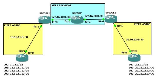
Here is our topology (same topology like with the other protocols used):

Given:
– a small MPLS backbone with SPCORE as P-Router (MPLS only, no BGP), SPEDGE routers as PE-Routers with MP-BGP enabled
– fa0/1 of the SPEDGE routers are in vrf “CUSTOMER”
– on the SP routers there is an OSPF process “1” which is used for backbone connectivity for the MP-BGP routers and for LDP
– some loopback interfaces which simulate networks connected to the SITE routers

Challenge:
– configure OSPF as the PE-CE routing protocol and make sure that the networks of SITE1 and SITE2 can reach each other via the MPLS VPN backbone.

Here is the config part of the SP routers (the routing protocol part):

SPCORE (MPLS and OSPF “1” only for backbone connectivity)

SPCORE#sh run | sec router
router ospf 1
 router-id 10.10.10.1
 log-adjacency-changes

SPEDGE1 (MPLS, OSPF backbone and MP-BGP)

SPEDGE1(config)#do sh run | sec router 
router ospf 1
 router-id 10.10.10.2
 log-adjacency-changes
router bgp 1
 no synchronization
 bgp log-neighbor-changes
 neighbor 10.10.10.3 remote-as 1
 neighbor 10.10.10.3 update-source Loopback0
 neighbor 10.10.10.3 next-hop-self
 neighbor 10.10.10.3 send-community both
 no auto-summary
 !
 address-family vpnv4
  neighbor 10.10.10.3 activate
  neighbor 10.10.10.3 send-community both
  neighbor 10.10.10.3 next-hop-self
 exit-address-family
 !
 address-family ipv4 vrf CUSTOMER
  no synchronization
 exit-address-family

SPEDGE2 (MPLS, OSPF backbone and MP-BGP)

SPEDGE2#sh run | sec router
router ospf 1
 router-id 10.10.10.3
 log-adjacency-changes
router bgp 1
 no synchronization
 bgp log-neighbor-changes
 neighbor 10.10.10.2 remote-as 1
 neighbor 10.10.10.2 update-source Loopback0
 neighbor 10.10.10.2 next-hop-self
 neighbor 10.10.10.2 send-community extended
 no auto-summary
 !
 address-family vpnv4
  neighbor 10.10.10.2 activate
  neighbor 10.10.10.2 send-community both
  neighbor 10.10.10.2 next-hop-self
 exit-address-family
 !
 address-family ipv4 vrf CUSTOMER
  no synchronization
 exit-address-family

So lets start with configuring OSPF on the SITE routers.

SITE1(config-if)#router ospf 1    
SITE1(config-router)#router-id 1.1.1.1
SITE1(config-router)#redistribute connected subnets
SITE1(config-router)#int fa0/0
SITE1(config-if)#ip ospf 1 are 0
!
SITE2(config)#router ospf 1
SITE2(config-router)#router-id 2.2.2.2
SITE2(config-router)#redistribute connected subnets
SITE2(config-router)#int fa0/0
SITE2(config-if)#ip ospf 1 are 0

Ok so far so good. We will now enter the configuration for the SPEDGE routers. As you can see now, there is no such thing like address families. We need to generate a separate OSPF process and bind this process to the corresponding vrf.

SPEDGE1(config)#router ospf 2 vrf CUSTOMER
SPEDGE1(config-router)#router-id 10.10.11.1
SPEDGE1(config-router)#int fa0/1
SPEDGE1(config-if)#ip ospf 2 are 0
!
SPEDGE2(config)#router ospf 2 vrf CUSTOMER
SPEDGE2(config-router)#router-id 10.10.22.1
SPEDGE2(config-router)#int fa0/1
SPEDGE2(config-if)#ip ospf 2 are 0

We can then see our adjacencies coming up!

SITE1#sh ip o n
!
Neighbor ID     Pri   State           Dead Time   Address         Interface
10.10.11.1        1   FULL/BDR        00:00:36    10.10.11.1      FastEthernet0/0
!
SITE2#sh ip ospf ne  
!
Neighbor ID     Pri   State           Dead Time   Address         Interface
10.10.22.1        1   FULL/BDR        00:00:29    10.10.22.1      FastEthernet0/0

When checking the routing tables we can see that we dont have ALL routes in the routing table. For example at SITE1 we are missing the networks of SITE2 and vice versa.

SITE1#sh ip route ospf
!
SITE1#

Nothing! Well thats quite logical because we have not configured mutual redistribution between OSPF and BGP yet. Lets do this. (By the way, on the SPEDGE routers you now should see the OSPF routes of the attached SITE router).

SPEDGE1#sh ip route vrf CUSTOMER ospf
!
Routing Table: CUSTOMER
!
     1.0.0.0/32 is subnetted, 1 subnets
O E2    1.1.1.1 [110/20] via 10.10.11.2, 00:03:31, FastEthernet0/1
     11.0.0.0/32 is subnetted, 3 subnets
O E2    11.11.11.11 [110/20] via 10.10.11.2, 00:03:31, FastEthernet0/1
O E2    11.11.11.13 [110/20] via 10.10.11.2, 00:03:31, FastEthernet0/1
O E2    11.11.11.12 [110/20] via 10.10.11.2, 00:03:31, FastEthernet0/1

So here is the config of BGP and OSPF on the SPEDGE routers:

SPEDGE1(config-router)#router ospf 2 vrf CUSTOMER           
SPEDGE1(config-router)#redistribute bgp 1 metric 100 subnets
SPEDGE1(config-router)#router bgp 1
SPEDGE1(config-router)#address-family ipv4 unicast vrf CUSTOMER
SPEDGE1(config-router-af)#redistribute ospf 2 metric 100 match internal external
!
SPEDGE2(config)#router ospf 2 vrf CUSTOMER
SPEDGE2(config-router)#redistribute bgp 1 metric 100 subnets 
SPEDGE2(config-router)#router bgp 1
SPEDGE2(config-router)#address-family ipv4 unicast vrf CUSTOMER
SPEDGE2(config-router-af)#redistribute ospf 2 metric 100 match internal external

We should now have all networks in the BGP table and after that we can check the site routers if they are receiving OSPF routes from the MPLS backbone.

SPEDGE1#sh ip bgp vpnv4 all
BGP table version is 282, local router ID is 10.10.10.2
Status codes: s suppressed, d damped, h history, * valid, > best, i - internal,
              r RIB-failure, S Stale
Origin codes: i - IGP, e - EGP, ? - incomplete

   Network          Next Hop            Metric LocPrf Weight Path
Route Distinguisher: 1:1 (default for vrf CUSTOMER)
*> 1.1.1.1/32       10.10.11.2             100         32768 ?
*>i2.2.2.2/32       10.10.10.3             100    100      0 ?
*> 10.10.11.0/30    0.0.0.0                  0         32768 ?
*>i10.10.22.0/30    10.10.10.3               0    100      0 ?
*> 11.11.11.11/32   10.10.11.2             100         32768 ?
*> 11.11.11.12/32   10.10.11.2             100         32768 ?
*> 11.11.11.13/32   10.10.11.2             100         32768 ?
*>i22.22.22.21/32   10.10.10.3             100    100      0 ?
*>i22.22.22.22/32   10.10.10.3             100    100      0 ?
*>i22.22.22.23/32   10.10.10.3             100    100      0 ?
*>i192.168.11.0/30  10.10.10.3             100    100      0 ?
!
SPEDGE2#sh ip bgp vpnv4 al
BGP table version is 277, local router ID is 10.10.10.3
Status codes: s suppressed, d damped, h history, * valid, > best, i - internal,
              r RIB-failure, S Stale
Origin codes: i - IGP, e - EGP, ? - incomplete   Network          Next Hop            Metric LocPrf Weight Path
Route Distinguisher: 1:1 (default for vrf CUSTOMER)
*>i1.1.1.1/32       10.10.10.2             100    100      0 ?
*> 2.2.2.2/32       10.10.22.2             100         32768 ?
*>i10.10.11.0/30    10.10.10.2               0    100      0 ?
*> 10.10.22.0/30    0.0.0.0                  0         32768 ?
*>i11.11.11.11/32   10.10.10.2             100    100      0 ?
*>i11.11.11.12/32   10.10.10.2             100    100      0 ?
*>i11.11.11.13/32   10.10.10.2             100    100      0 ?
*> 22.22.22.21/32   10.10.22.2             100         32768 ?
*> 22.22.22.22/32   10.10.22.2             100         32768 ?
*> 22.22.22.23/32   10.10.22.2             100         32768 ?
*> 192.168.11.0/30  10.10.22.2             100         32768 ?

Looks good. Lets check the routing tables of the site routers.

SITE1#sh ip route ospf
     2.0.0.0/32 is subnetted, 1 subnets
O E2    2.2.2.2 [110/100] via 10.10.11.1, 00:00:43, FastEthernet0/0
     22.0.0.0/32 is subnetted, 3 subnets
O E2    22.22.22.22 [110/100] via 10.10.11.1, 00:00:43, FastEthernet0/0
O E2    22.22.22.23 [110/100] via 10.10.11.1, 00:00:43, FastEthernet0/0
O E2    22.22.22.21 [110/100] via 10.10.11.1, 00:00:43, FastEthernet0/0
     10.0.0.0/30 is subnetted, 2 subnets
O IA    10.10.22.0 [110/110] via 10.10.11.1, 00:03:12, FastEthernet0/0
!
SITE2#sh ip route ospf
     1.0.0.0/32 is subnetted, 1 subnets
O E2    1.1.1.1 [110/100] via 10.10.22.1, 00:01:24, FastEthernet0/0
     10.0.0.0/30 is subnetted, 2 subnets
O IA    10.10.11.0 [110/110] via 10.10.22.1, 00:03:34, FastEthernet0/0
     11.0.0.0/32 is subnetted, 3 subnets
O E2    11.11.11.11 [110/100] via 10.10.22.1, 00:01:24, FastEthernet0/0
O E2    11.11.11.13 [110/100] via 10.10.22.1, 00:01:24, FastEthernet0/0
O E2    11.11.11.12 [110/100] via 10.10.22.1, 00:01:24, FastEthernet0/0

Perfect! Lets check the connectivity to see if the VPN labels are used correctly in the MPLS backbone.

SITE1#ping 22.22.22.22 so lo1
!
Type escape sequence to abort.
Sending 5, 100-byte ICMP Echos to 22.22.22.22, timeout is 2 seconds:
Packet sent with a source address of 11.11.11.11 
!!!!!
Success rate is 100 percent (5/5), round-trip min/avg/max = 76/136/172 ms

So thats it :). I hope you enjoyed this little post.
Feel free to comment!
Regards!
Markus

Posted in MPLS, Routing | Tagged , , , , , , , , , , , , , , , , , | 2 Comments

mpls: layer3-vpns, pe-ce routing protocol – eigrp

Hello everyone!
Right now I am going to show how to use EIGRP as a PE-CE routing protocol when using MPLS VPNs.

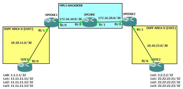
Here is our topology (same topology like with the other protocols used):

Given:
– a small MPLS backbone with SPCORE as P-Router (MPLS only, no BGP), SPEDGE routers as PE-Routers with MP-BGP enabled
– fa0/1 of the SPEDGE routers are in vrf “CUSTOMER”
– on the SP routers there is an OSPF process “1” which is used for backbone connectivity for the MP-BGP routers and for LDP
– some loopback interfaces which simulate networks connected to the SITE routers

Challenge:
– configure EIGRP as the PE-CE routing protocol and make sure that the networks of SITE1 and SITE2 can reach each other via the MPLS VPN backbone.

Here is the config part of the SP routers (the routing protocol part):

SPCORE (MPLS and OSPF “1” only for backbone connectivity)

SPCORE#sh run | sec router
router ospf 1
 router-id 10.10.10.1
 log-adjacency-changes

SPEDGE1 (MPLS, OSPF backbone and MP-BGP)

SPEDGE1(config)#do sh run | sec router 
router ospf 1
 router-id 10.10.10.2
 log-adjacency-changes
router bgp 1
 no synchronization
 bgp log-neighbor-changes
 neighbor 10.10.10.3 remote-as 1
 neighbor 10.10.10.3 update-source Loopback0
 neighbor 10.10.10.3 next-hop-self
 neighbor 10.10.10.3 send-community both
 no auto-summary
 !
 address-family vpnv4
  neighbor 10.10.10.3 activate
  neighbor 10.10.10.3 send-community both
  neighbor 10.10.10.3 next-hop-self
 exit-address-family
 !
 address-family ipv4 vrf CUSTOMER
  no synchronization
 exit-address-family

SPEDGE2 (MPLS, OSPF backbone and MP-BGP)

SPEDGE2#sh run | sec router
router ospf 1
 router-id 10.10.10.3
 log-adjacency-changes
router bgp 1
 no synchronization
 bgp log-neighbor-changes
 neighbor 10.10.10.2 remote-as 1
 neighbor 10.10.10.2 update-source Loopback0
 neighbor 10.10.10.2 next-hop-self
 neighbor 10.10.10.2 send-community extended
 no auto-summary
 !
 address-family vpnv4
  neighbor 10.10.10.2 activate
  neighbor 10.10.10.2 send-community both
  neighbor 10.10.10.2 next-hop-self
 exit-address-family
 !
 address-family ipv4 vrf CUSTOMER
  no synchronization
 exit-address-family

So lets start with configuring EIGRP (we use AS100 for our AS number) on the SITE-routers.

SITE1(config)#router eigrp 100
SITE1(config-router)#no auto
SITE1(config-router)#network 10.10.11.0 0.0.0.255 
SITE1(config-router)#redistribute connected metric 10000 10 255 1 1500
!
SITE2(config)#router eigrp 100
SITE2(config-router)#no auto 
SITE2(config-router)#network 10.10.22.0 0.0.0.255
SITE2(config-router)#redistribute connected metric 10000 10 255 1 1500

Ok good. Now we need to do the same on the SPEDGE routers to build an adjacency between the SITE and the SPEDGE routers. Here you can see again that the configuration is like BGP, you can use address families.

SPEDGE1(config)#router eigrp 100
SPEDGE1(config-router)#address-family ipv4 unicast vrf CUSTOMER
SPEDGE1(config-router-af)#network 10.10.11.0 0.0.0.255
SPEDGE1(config-router-af)#no auto
!
SPEDGE2(config)#router eigrp 100
SPEDGE2(config-router)#address-family ipv4 unicast vrf CUSTOMER 
SPEDGE2(config-router-af)#no auto
SPEDGE2(config-router-af)#network 10.10.22.0 0.0.0.255

Ok configuration seems to be complete, lets check the adjacencies.

SPEDGE1#sh ip eigrp neigh
IP-EIGRP neighbors for process 100
SPEDGE1#

Hmm nothing…lets check SITE1 for EIGRP hellos.

SITE1#debug ip eigrp 100 
IP-EIGRP Route Events debugging is on
SITE1#debug ip eigrp summ
IP-EIGRP Summary route processing debugging is on
SITE1#debug ip pack
IP packet debugging is on
SITE1#
*Mar  1 03:35:42.459: IP: s=10.10.11.2 (local), d=224.0.0.10 (FastEthernet0/0), len 60, sending broad/multicast
SITE1#
*Mar  1 03:35:46.791: IP: s=10.10.11.2 (local), d=224.0.0.10 (FastEthernet0/0), len 60, sending broad/multicast
SITE1#
*Mar  1 03:35:51.575: IP: s=10.10.11.2 (local), d=224.0.0.10 (FastEthernet0/0), len 60, sending broad/multicast

Hmm strange…the SITE router is sending EIGRP hellos to 224.0.0.10 but we are not receiving hellos from the SPEDGE1 router (same behaviour we can see between SITE2 and SPEDGE2). Lets do a debug on SPEDGE1.

SPEDGE1#
*Mar  1 03:37:07.327: IP: s=172.16.10.1 (FastEthernet0/0), d=224.0.0.2, len 62, rcvd 0
SPEDGE1#
*Mar  1 03:37:08.779: IP: s=172.16.10.2 (local), d=224.0.0.2 (FastEthernet0/0), len 62, sending broad/multicast
*Mar  1 03:37:09.435: IP: s=172.16.10.2 (local), d=224.0.0.5 (FastEthernet0/0), len 80, sending broad/multicast
SPEDGE1#
*Mar  1 03:37:11.335: IP: s=172.16.10.1 (FastEthernet0/0), d=224.0.0.2, len 62, rcvd 0
*Mar  1 03:37:12.071: IP: s=172.16.10.1 (FastEthernet0/0), d=224.0.0.5, len 80, rcvd 0
SPEDGE1#
*Mar  1 03:37:13.175: IP: s=172.16.10.2 (local), d=224.0.0.2 (FastEthernet0/0), len 62, sending broad/multicast
SPEDGE1#
*Mar  1 03:37:15.999: IP: tableid=0, s=10.10.10.2 (local), d=10.10.10.1 (FastEthernet0/0), routed via FIB
*Mar  1 03:37:15.999: IP: s=10.10.10.2 (local), d=10.10.10.1 (FastEthernet0/0), len 58, sending
*Mar  1 03:37:16.099: IP: tableid=0, s=10.10.10.1 (FastEthernet0/0), d=10.10.10.2 (Loopback0), routed via RIB
*Mar  1 03:37:16.099: IP: s=10.10.10.1 (FastEthernet0/0), d=10.10.10.2, len 40, rcvd 4
*Mar  1 03:37:16.103: IP: s=172.16.10.1 (FastEthernet0/0), d=224.0.0.2, len 62, rcvd 0
SPEDGE1#
*Mar  1 03:37:17.167: IP: s=172.16.10.2 (local), d=224.0.0.2 (FastEthernet0/0), len 62, sending broad/multicast
SPEDGE1#
*Mar  1 03:37:18.811: IP: s=172.16.10.2 (local), d=224.0.0.5 (FastEthernet0/0), len 80, sending broad/multicast
SPEDGE1#
*Mar  1 03:37:20.211: IP: s=172.16.10.1 (FastEthernet0/0), d=224.0.0.2, len 62, rcvd 0
SPEDGE1#
*Mar  1 03:37:21.215: IP: s=172.16.10.2 (local), d=224.0.0.2 (FastEthernet0/0), len 62, sending broad/multicast
*Mar  1 03:37:21.515: IP: s=172.16.10.1 (FastEthernet0/0), d=224.0.0.5, len 80, rcvd 0
SPEDGE1#
*Mar  1 03:37:24.227: IP: s=172.16.10.1 (FastEthernet0/0), d=224.0.0.2, len 62, rcvd 0
SPEDGE1#
*Mar  1 03:37:26.135: IP: s=172.16.10.2 (local), d=224.0.0.2 (FastEthernet0/0), len 62, sending broad/multicast
SPEDGE1#
*Mar  1 03:37:28.299: IP: s=172.16.10.1 (FastEthernet0/0), d=224.0.0.2, len 62, rcvd 0
*Mar  1 03:37:28.519: IP: s=172.16.10.2 (local), d=224.0.0.5 (FastEthernet0/0), len 80, sending broad/multicast

Nothing about EIGRP. Well this has a specific reason. Although we used AS100 in the “router eigrp” command we need to specify the AS number for each address family and so for each VRF! without an AS number configured under the address-family the router will do nothing!

SPEDGE1(config-router)#router eigrp 100                        
SPEDGE1(config-router)#address-family ipv4 unicast vrf CUSTOMER
SPEDGE1(config-router-af)#autonomous-system 100
!
SPEDGE2(config)#router eigrp 100                        
SPEDGE2(config-router)#address-family ipv4 unicast vrf CUSTOMER
SPEDGE2(config-router-af)#autonomous-system 100

Now lets have a look at the adjacency-tables:

SPEDGE1#sh ip eigrp vrf CUSTOMER neigh
IP-EIGRP neighbors for process 100
H   Address                 Interface       Hold Uptime   SRTT   RTO  Q  Seq
                                            (sec)         (ms)       Cnt Num
0   10.10.11.2              Fa0/1             14 00:01:45  129   774  0  3
!
SPEDGE2#sh ip eigrp vrf CUSTOMER neigh
IP-EIGRP neighbors for process 100
H   Address                 Interface       Hold Uptime   SRTT   RTO  Q  Seq
                                            (sec)         (ms)       Cnt Num
0   10.10.22.2              Fa0/1             14 00:01:05  140   840  0  3

There we go! Now we need to configure mutual redistribution. EIGRP into BGP and backwards.

SPEDGE1(config)#router bgp 1
SPEDGE1(config-router)#address-family ipv4 unicast vrf CUSTOMER
SPEDGE1(config-router-af)#redistribute eigrp 100 metric 200
SPEDGE1(config-router-af)#router eigrp 100
SPEDGE1(config-router)#address-family ipv4 unicast vrf CUSTOMER
SPEDGE1(config-router-af)#redistribute bgp 1 metric 10000 10 255 1 1500
!
SPEDGE2(config)#router bgp 1
SPEDGE2(config-router)#address-family ipv4 unicast vrf CUSTOMER
SPEDGE2(config-router-af)#redistribute eigrp 100 metric 200
SPEDGE2(config-router-af)#router eigrp 100
SPEDGE2(config-router)#address-family ipv4 unicast vrf CUSTOMER
SPEDGE2(config-router-af)#redistribute bgp 1 metric 10000 10 255 1 1500

Now all prefixes should be present in the BGP VPNv4 table.

SPEDGE1#sh ip bgp vpnv4 all
BGP table version is 249, local router ID is 10.10.10.2
Status codes: s suppressed, d damped, h history, * valid, > best, i - internal,
              r RIB-failure, S Stale
Origin codes: i - IGP, e - EGP, ? - incomplete

   Network          Next Hop            Metric LocPrf Weight Path
Route Distinguisher: 1:1 (default for vrf CUSTOMER)
*> 1.1.1.1/32       10.10.11.2             200         32768 ?
*>i2.2.2.2/32       10.10.10.3             200    100      0 ?
*> 10.10.11.0/30    0.0.0.0                  0         32768 ?
*>i10.10.22.0/30    10.10.10.3               0    100      0 ?
*> 11.11.11.11/32   10.10.11.2             200         32768 ?
*> 11.11.11.12/32   10.10.11.2             200         32768 ?
*> 11.11.11.13/32   10.10.11.2             200         32768 ?
*>i22.22.22.21/32   10.10.10.3             200    100      0 ?
*>i22.22.22.22/32   10.10.10.3             200    100      0 ?
*>i22.22.22.23/32   10.10.10.3             200    100      0 ?
*>i192.168.11.0/30  10.10.10.3             200    100      0 ?
!
SPEDGE2#sh ip bgp vpnv4 all
BGP table version is 249, local router ID is 10.10.10.3
Status codes: s suppressed, d damped, h history, * valid, > best, i - internal,
              r RIB-failure, S Stale
Origin codes: i - IGP, e - EGP, ? - incomplete   Network          Next Hop            Metric LocPrf Weight Path
Route Distinguisher: 1:1 (default for vrf CUSTOMER)
*>i1.1.1.1/32       10.10.10.2             200    100      0 ?
*> 2.2.2.2/32       10.10.22.2             200         32768 ?
*>i10.10.11.0/30    10.10.10.2               0    100      0 ?
*> 10.10.22.0/30    0.0.0.0                  0         32768 ?
*>i11.11.11.11/32   10.10.10.2             200    100      0 ?
*>i11.11.11.12/32   10.10.10.2             200    100      0 ?
*>i11.11.11.13/32   10.10.10.2             200    100      0 ?
*> 22.22.22.21/32   10.10.22.2             200         32768 ?
*> 22.22.22.22/32   10.10.22.2             200         32768 ?
*> 22.22.22.23/32   10.10.22.2             200         32768 ?
*> 192.168.11.0/30  10.10.22.2             200         32768 ?

Looks nice! Lets check the SITE routers for EIGRP networks.

SITE1#sh ip route eigrp
     2.0.0.0/32 is subnetted, 1 subnets
D EX    2.2.2.2 [170/309760] via 10.10.11.1, 00:01:20, FastEthernet0/0
     22.0.0.0/32 is subnetted, 3 subnets
D EX    22.22.22.22 [170/309760] via 10.10.11.1, 00:01:20, FastEthernet0/0
D EX    22.22.22.23 [170/309760] via 10.10.11.1, 00:01:20, FastEthernet0/0
D EX    22.22.22.21 [170/309760] via 10.10.11.1, 00:01:20, FastEthernet0/0
     10.0.0.0/30 is subnetted, 2 subnets
D       10.10.22.0 [90/307200] via 10.10.11.1, 00:01:20, FastEthernet0/0
!
SITE2#sh ip route eigrp  
     1.0.0.0/32 is subnetted, 1 subnets
D EX    1.1.1.1 [170/309760] via 10.10.22.1, 00:01:38, FastEthernet0/0
     10.0.0.0/30 is subnetted, 2 subnets
D       10.10.11.0 [90/307200] via 10.10.22.1, 00:01:38, FastEthernet0/0
     11.0.0.0/32 is subnetted, 3 subnets
D EX    11.11.11.11 [170/309760] via 10.10.22.1, 00:01:38, FastEthernet0/0
D EX    11.11.11.13 [170/309760] via 10.10.22.1, 00:01:38, FastEthernet0/0
D EX    11.11.11.12 [170/309760] via 10.10.22.1, 00:01:38, FastEthernet0/0

Looks good. The routes of the opposite SITE router are marked with “EX” for EXTERNAL. This is because we are injecting the loopback addresses with the “redistribute connected” command, so for EIGRP this means that the routes come from an EXTERNAL routing protocol (in our case “static /connected routing”).

Lets do the final connectivity check to see if the VPN labels are working fine!

SITE1#ping 22.22.22.22 so lo1
!
Type escape sequence to abort.
Sending 5, 100-byte ICMP Echos to 22.22.22.22, timeout is 2 seconds:
Packet sent with a source address of 11.11.11.11 
!!!!!
Success rate is 100 percent (5/5), round-trip min/avg/max = 104/139/156 ms

Looks good!
I hope you enjoyed this post! Feel free comment!
Regards!
Markus

Posted in MPLS, Routing | Tagged , , , , , , , , , , , , , , , , , , , | 1 Comment

mpls: layer3-vpns, pe-ce routing protocol – rip

Hello everyone!
Today I am going to show how to use a variety of routing protocols to be used as PE-CE routing protocol when you are connected to a MPLS VPN service provider or when you act as a provider.

First protocol will be RIPv2.

Here is our topology:

Given:
– a small MPLS backbone with SPCORE as P-Router (MPLS only, no BGP), SPEDGE routers as PE-Routers with MP-BGP enabled
– fa0/1 of the SPEDGE routers are in vrf “CUSTOMER”
– on the SP routers there is an OSPF process “1” which is used for backbone connectivity for the MP-BGP routers and for LDP
– some loopback interfaces which simulate networks connected to the SITE routers

Challenge:
– configure RIPv2 as the PE-CE routing protocol and make sure that the networks of SITE1 and SITE2 can reach each other via the MPLS VPN backbone.

Here is the config part of the SP routers (the routing protocol part):

SPCORE (MPLS and OSPF “1” only for backbone connectivity)

SPCORE#sh run | sec router
router ospf 1
 router-id 10.10.10.1
 log-adjacency-changes

SPEDGE1 (MPLS, OSPF backbone and MP-BGP)

SPEDGE1(config)#do sh run | sec router 
router ospf 1
 router-id 10.10.10.2
 log-adjacency-changes
router bgp 1
 no synchronization
 bgp log-neighbor-changes
 neighbor 10.10.10.3 remote-as 1
 neighbor 10.10.10.3 update-source Loopback0
 neighbor 10.10.10.3 next-hop-self
 neighbor 10.10.10.3 send-community both
 no auto-summary
 !
 address-family vpnv4
  neighbor 10.10.10.3 activate
  neighbor 10.10.10.3 send-community both
  neighbor 10.10.10.3 next-hop-self
 exit-address-family
 !
 address-family ipv4 vrf CUSTOMER
  no synchronization
 exit-address-family

SPEDGE2 (MPLS, OSPF backbone and MP-BGP)

SPEDGE2#sh run | sec router
router ospf 1
 router-id 10.10.10.3
 log-adjacency-changes
router bgp 1
 no synchronization
 bgp log-neighbor-changes
 neighbor 10.10.10.2 remote-as 1
 neighbor 10.10.10.2 update-source Loopback0
 neighbor 10.10.10.2 next-hop-self
 neighbor 10.10.10.2 send-community extended
 no auto-summary
 !
 address-family vpnv4
  neighbor 10.10.10.2 activate
  neighbor 10.10.10.2 send-community both
  neighbor 10.10.10.2 next-hop-self
 exit-address-family
 !
 address-family ipv4 vrf CUSTOMER
  no synchronization
 exit-address-family

So lets start with configuring RIPv2 on the SITE-routers. Thatll be an easy one.

SITE1(config)#router rip 
SITE1(config-router)#no auto
SITE1(config-router)#version 2
SITE1(config-router)#network 10.10.11.0  
SITE1(config-router)#redistribute connected metric 1
!
SITE2(config)#router rip 
SITE2(config-router)#no auto
SITE2(config-router)#version 2
SITE2(config-router)#network 10.10.22.0 
SITE2(config-router)#redistribute connected metric 1

Ok so far so good. Now we need to do the same on the SPEDGE routers. You will see that the configuration is almost like in BGP! You also have the possbility to use address-families. Take a look here:

SPEDGE1(config)#router rip
SPEDGE1(config-router)#address-family ipv4 unicast vrf CUSTOMER
SPEDGE1(config-router-af)#no auto
SPEDGE1(config-router-af)#version 2
SPEDGE1(config-router-af)#network 10.10.11.0
!
SPEDGE2(config)#router rip 
SPEDGE2(config-router)#address-family ipv4 unicast vrf CUSTOMER
SPEDGE2(config-router-af)#no auto 
SPEDGE2(config-router-af)#version 2
SPEDGE2(config-router-af)#network 10.10.22.0 

Lets have a look at the routing tables in the VRFs and if we are able to see the SITE-networks on the SPEDGE routers.

SPEDGE1#sh ip route vrf CUSTOMER rip 
     1.0.0.0/32 is subnetted, 1 subnets
R       1.1.1.1 [120/1] via 10.10.11.2, 00:00:03, FastEthernet0/1
     192.168.11.0/30 is subnetted, 1 subnets
R       192.168.11.0 [120/1] via 10.10.11.2, 00:00:03, FastEthernet0/1
     11.0.0.0/32 is subnetted, 3 subnets
R       11.11.11.11 [120/1] via 10.10.11.2, 00:00:03, FastEthernet0/1
R       11.11.11.13 [120/1] via 10.10.11.2, 00:00:03, FastEthernet0/1
R       11.11.11.12 [120/1] via 10.10.11.2, 00:00:03, FastEthernet0/1
!
SPEDGE2#sh ip route vrf CUSTOMER rip
     2.0.0.0/32 is subnetted, 1 subnets
R       2.2.2.2 [120/1] via 10.10.22.2, 00:00:25, FastEthernet0/1
     192.168.11.0/30 is subnetted, 1 subnets
R       192.168.11.0 [120/1] via 10.10.22.2, 00:00:25, FastEthernet0/1
     22.0.0.0/32 is subnetted, 3 subnets
R       22.22.22.22 [120/1] via 10.10.22.2, 00:00:25, FastEthernet0/1
R       22.22.22.23 [120/1] via 10.10.22.2, 00:00:25, FastEthernet0/1
R       22.22.22.21 [120/1] via 10.10.22.2, 00:00:25, FastEthernet0/1

There we go! The only problem we now have is that SPEDGE1 doesnt see the routes SPEDGE2 has in its tables, although its the same VRF. Well, the reason for this is that we dont redistribute RIP into MP-BGP. We need to do this to perfom an exchange over the MPLS backbone, so that all routers that have the vrf “CUSTOMER” attached get those routes. And of course dont forget to do the redistribution mutually!!! You also need to redistribute MP-BGP into the RIP process. If not, then SPEDGE1 gets the routes of SITE2 but doesnt hand them over to SITE1.

SPEDGE1(config)#router bgp 1
SPEDGE1(config-router)#address-family ipv4 unicast vrf CUSTOMER
SPEDGE1(config-router-af)#redistribute rip metric 10
SPEDGE1(config-router-af)#router rip 
SPEDGE1(config-router)#address-family ipv4 unicast vrf CUSTOMER
SPEDGE1(config-router-af)#redistribute bgp 1 metric transparent  
!
SPEDGE2(config)#router bgp 1
SPEDGE2(config-router)#address-family ipv4 unicast vrf CUSTOMER
SPEDGE2(config-router-af)#redistribute rip metric 10
SPEDGE2(config-router-af)#router rip
SPEDGE2(config-router)#address-family ipv4 unicast vrf CUSTOMER
SPEDGE2(config-router-af)#redistribute bgp 1 metric transparent

So far so good. Lets take a look at the VPNv4 BGP tables of the SPEDGE routers. There we should see all networks from the SITE routers.

SPEDGE1#sh ip bgp 
*Mar  1 02:27:22.167: %SYS-5-CONFIG_I: Configured from console by console
SPEDGE1#sh ip bgp vpnv4 all 
BGP table version is 214, local router ID is 10.10.10.2
Status codes: s suppressed, d damped, h history, * valid, > best, i - internal,
              r RIB-failure, S Stale
Origin codes: i - IGP, e - EGP, ? - incomplete

   Network          Next Hop            Metric LocPrf Weight Path
Route Distinguisher: 1:1 (default for vrf CUSTOMER)
*> 1.1.1.1/32       10.10.11.2              10         32768 ?
*>i2.2.2.2/32       10.10.10.3              10    100      0 ?
*> 10.10.11.0/30    0.0.0.0                  0         32768 ?
*>i10.10.22.0/30    10.10.10.3               0    100      0 ?
*> 11.11.11.11/32   10.10.11.2              10         32768 ?
*> 11.11.11.12/32   10.10.11.2              10         32768 ?
*> 11.11.11.13/32   10.10.11.2              10         32768 ?
*>i22.22.22.21/32   10.10.10.3              10    100      0 ?
*>i22.22.22.22/32   10.10.10.3              10    100      0 ?
*>i22.22.22.23/32   10.10.10.3              10    100      0 ?
* i192.168.11.0/30  10.10.10.3              10    100      0 ?
*>                  10.10.11.2              10         32768 ?
!
SPEDGE2#sh ip bgp vpnv4 all
BGP table version is 216, local router ID is 10.10.10.3
Status codes: s suppressed, d damped, h history, * valid, > best, i - internal,
              r RIB-failure, S Stale
Origin codes: i - IGP, e - EGP, ? - incomplete   Network          Next Hop            Metric LocPrf Weight Path
Route Distinguisher: 1:1 (default for vrf CUSTOMER)
*>i1.1.1.1/32       10.10.10.2              10    100      0 ?
*> 2.2.2.2/32       10.10.22.2              10         32768 ?
*>i10.10.11.0/30    10.10.10.2               0    100      0 ?
*> 10.10.22.0/30    0.0.0.0                  0         32768 ?
*>i11.11.11.11/32   10.10.10.2              10    100      0 ?
*>i11.11.11.12/32   10.10.10.2              10    100      0 ?
*>i11.11.11.13/32   10.10.10.2              10    100      0 ?
*> 22.22.22.21/32   10.10.22.2              10         32768 ?
*> 22.22.22.22/32   10.10.22.2              10         32768 ?
*> 22.22.22.23/32   10.10.22.2              10         32768 ?
*> 192.168.11.0/30  10.10.22.2              10         32768 ?
* i                 10.10.10.2              10    100      0 ?

That looks quite confident. All networks are in the MP-BGP table which is good because this means that the RIP networks are transported via the MPLS backbone. Lets check this on the site routers.

SITE1#sh ip route rip
     2.0.0.0/32 is subnetted, 1 subnets
R       2.2.2.2 [120/11] via 10.10.11.1, 00:00:24, FastEthernet0/0
     22.0.0.0/32 is subnetted, 3 subnets
R       22.22.22.22 [120/11] via 10.10.11.1, 00:00:24, FastEthernet0/0
R       22.22.22.23 [120/11] via 10.10.11.1, 00:00:24, FastEthernet0/0
R       22.22.22.21 [120/11] via 10.10.11.1, 00:00:24, FastEthernet0/0
     10.0.0.0/30 is subnetted, 2 subnets
R       10.10.22.0 [120/1] via 10.10.11.1, 00:00:24, FastEthernet0/0
!
SITE2#sh ip route rip
     1.0.0.0/32 is subnetted, 1 subnets
R       1.1.1.1 [120/11] via 10.10.22.1, 00:00:21, FastEthernet0/0
     10.0.0.0/30 is subnetted, 2 subnets
R       10.10.11.0 [120/1] via 10.10.22.1, 00:00:21, FastEthernet0/0
     11.0.0.0/32 is subnetted, 3 subnets
R       11.11.11.11 [120/11] via 10.10.22.1, 00:00:21, FastEthernet0/0
R       11.11.11.13 [120/11] via 10.10.22.1, 00:00:21, FastEthernet0/0
R       11.11.11.12 [120/11] via 10.10.22.1, 00:00:21, FastEthernet0/0

Works! Ok lets now test the reachbility between the two systems, to see if the MPLS forwarding and the MPLS VPN label assignment works properly.

SITE1#ping 22.22.22.22 so lo1
!
Type escape sequence to abort.
Sending 5, 100-byte ICMP Echos to 22.22.22.22, timeout is 2 seconds:
Packet sent with a source address of 11.11.11.11 
!!!!!
Success rate is 100 percent (5/5), round-trip min/avg/max = 120/144/176 ms

Perfect!
So we are done with this part here!

I hope you enjoyed reading!
Feel free to comment!

Regards!
Markus

Posted in MPLS, Routing, Uncategorized | Tagged , , , , , , , , , , , , , | Leave a comment

mpls: ospf sham link – why? and howto!

Hello everybody.
Today I decided to write a post about OSPF SHAM LINK which is used in MPLS networks.
Before giving a short explanation for what the sham link is used I will show you the topology as its a little bit easier to understand then.

Topology:
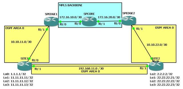
Given:
– a small MPLS backbone with SPCORE as P-Router (MPLS only, no BGP), SPEDGE routers as PE-Routers with MP-BGP enabled
– fa0/1 of the SPEDGE routers are in vrf “CUSTOMER”
– OSPF as PE-CE routing protocol between SITE and SPEDGE routers
– on SPEDGE routers the OSPF process ID is “2” for the “CUSTOMER” vrf and OSPF process ID is “1” for the MPLS Backbone connectivity
– a backup link between the SITE routers which is also in AREA 0 for the case if the ISP breaks down
– some loopback interfaces which simulate networks connected to the SITE routers

Motivation:
Well what is OSPF SHAM LINK and whats it good for. I will only briefly explain it here because during the configuration you will get some details in how to configure it. An OSPF sham link addresses the problem that you will encounter in such a scenario. For example lets take SITE1. Lets assume the backup link does not exist then whats happening? Well SITE1 shall recieve the networks from SITE2 via the ISP network. The process here is the following

1) SITE2 injects the networks into OSPF
2) SPEDGE2 get those networks from SITE2 via OSPF
3) SPEDGE2 redistributes the networks from OSPF into MP-BGP and the corresponding VRF
4) The networks are transported via BGP to SPEDGE1 and SPEDGE1 sees those networks in the BGP table
5) SPEDGE1 redistributes the networks into the OSPF process for SITE1
6) SPEDGE1 sends the networks to SITE1 via OSPF
7) SITE1 gets the networks via OSPF and installs the routes in its routing table

…BUT!!!…

Point 7 is only the half of the truth. SITE1 installs the networks in its routing table but what type of OSPF routes are we dealing with? Well as the routes are redistributed from a different protocol (BGP) into OSPF they should usually be E1 or E2 routes. But they are not, as BGP is capable of carrying OSPF information. SITE1 has an OSPF adjacency with SPEDGE1 and not directly with SITE2 (except if we fire up the backup link, but more on that later) which means that it SITE1 sees the routes from a router from the same AREA but its not directly connected. This has the effect that the routes are received by SITE1 as “IA” (INTER AREA) routes. So and here comes the problem.
Usually you would think “Hey okay…I sent my traffic through the ISP and if the ISP fails, then the traffic is sent via the BACKUP LINK”. Good idea, how does one realize that usually? Right! With OSPF cost. So if you raise the OSPF on the backup link to “10000” and the cost for the link to the ISP is lets say “10” then everybody would say “Of course the traffic is going through the ISP!”. But ITS NOT :).
But why? Well OSPF prefers INTRA-AREA-routes (normal “O” routes) over INTER-AREA-routes (“IA” routes), no matter what cost you configure.
The solution to that is the OSPF sham link. Later on in the text I will provide more details.

Challenges:
– configure OSPF end to end connectivity between SITE1 and SITE2 via the ISP
– leave the backup link shutdown in the first place
– when succeeded then open up the BACKUP LINK and take a look at the problem
– configure an OSPF sham link to conquer the problem
– the need for mutual redsitribution of BGP/OSPF?

So here we go. we assume that our ISP routers are configured properly, i.e. OSPF is activated, MP-BGP is running and the VRF is configured including the proper ip addresses. Here is the relevant config for the backbone.

SPCORE (only MPLS enabled routes w/o BGP):

hostname SPCORE
!
ip cef
!
interface Loopback0
 ip address 10.10.10.1 255.255.255.255
 ip ospf 1 area 0
!
interface FastEthernet0/0
 ip address 172.16.10.1 255.255.255.252
 ip ospf 1 area 0
 duplex auto
 speed auto
 mpls ip
!
interface FastEthernet0/1
 ip address 172.16.20.1 255.255.255.252
 ip ospf 1 area 0
 duplex auto
 speed auto
 mpls ip
!
!
!
router ospf 1
 router-id 10.10.10.1
 log-adjacency-changes
!
!
!
mpls ldp router-id Loopback0 force

SPEDGE1 (edge router with MBGP and VRF enabled):

hostname SPEDGE1
!
ip cef
!
!
ip vrf CUSTOMER
 rd 1:1
 route-target export 1:1
 route-target import 1:1
!
!
!
interface Loopback0
 ip address 10.10.10.2 255.255.255.255
 ip ospf 1 area 0
!
interface FastEthernet0/0
 ip address 172.16.10.2 255.255.255.252
 ip ospf 1 area 0
 duplex auto
 speed auto
 mpls ip
!
interface FastEthernet0/1
 ip vrf forwarding CUSTOMER
 ip address 10.10.11.1 255.255.255.252
 ip ospf 2 area 0
 duplex auto
 speed auto
!
!
!
router ospf 2 vrf CUSTOMER
 router-id 10.10.11.1
 log-adjacency-changes
 redistribute bgp 1 metric 200 subnets
!
router ospf 1
 router-id 10.10.10.2
 log-adjacency-changes
!         
router bgp 1
 no synchronization
 bgp log-neighbor-changes
 neighbor 10.10.10.3 remote-as 1
 neighbor 10.10.10.3 update-source Loopback0
 neighbor 10.10.10.3 next-hop-self
 neighbor 10.10.10.3 send-community both
 no auto-summary
 !
 address-family vpnv4
  neighbor 10.10.10.3 activate
  neighbor 10.10.10.3 send-community both
  neighbor 10.10.10.3 next-hop-self
 exit-address-family
 !
 address-family ipv4 vrf CUSTOMER
  redistribute ospf 2 vrf CUSTOMER metric 200 match internal external
  no synchronization
 exit-address-family
!
!
!
mpls ldp router-id Loopback0 force

SPEDGE2 (edge router with MBGP and VRF enabled):

hostname SPEDGE2
!
ip cef
!
!
!
ip vrf CUSTOMER
 rd 1:1
 route-target export 1:1
 route-target import 1:1
!
!
!
interface Loopback0
 ip address 10.10.10.3 255.255.255.255
 ip ospf 1 area 0
!
interface FastEthernet0/0
 ip address 172.16.20.2 255.255.255.252
 ip ospf 1 area 0
 duplex auto
 speed auto
 mpls ip
!
interface FastEthernet0/1
 ip vrf forwarding CUSTOMER
 ip address 10.10.22.1 255.255.255.252
 ip ospf 2 area 0
 duplex auto
 speed auto
!
!
!
router ospf 2 vrf CUSTOMER
 router-id 10.10.22.1
 log-adjacency-changes
 redistribute bgp 1 metric 200 subnets
!
router ospf 1
 router-id 10.10.10.3
 log-adjacency-changes
!         
router bgp 1
 no synchronization
 bgp log-neighbor-changes
 neighbor 10.10.10.2 remote-as 1
 neighbor 10.10.10.2 update-source Loopback0
 neighbor 10.10.10.2 next-hop-self
 neighbor 10.10.10.2 send-community extended
 no auto-summary
 !
 address-family vpnv4
  neighbor 10.10.10.2 activate
  neighbor 10.10.10.2 send-community both
  neighbor 10.10.10.2 next-hop-self
 exit-address-family
 !
 address-family ipv4 vrf CUSTOMER
  redistribute ospf 2 vrf CUSTOMER metric 200 match internal external
  no synchronization
 exit-address-family
!
!
!
mpls ldp router-id Loopback0 force

Ok then lets now configure the OSPF adjacency between SITE1 and SPEDGE1 and SITE2 and SPEDGE2, that should be an easy one.

SITE1(config)#int fa0/0
SITE1(config-if)#no shut
SITE1(config-if)#ip address 10.10.11.2 255.255.255.252
SITE1(config-if)#ip ospf 1 are 0
SITE1(config-if)#int fa0/1                            
SITE1(config-if)#ip address 192.168.11.1 255.255.255.252  
SITE1(config-if)#shut                                
SITE1(config-if)#ip ospf 1 are 0
SITE1(config-if)#router ospf 1
SITE1(config-router)#redistribute connected subnets 
!
SITE2(config)#int fa0/0
SITE2(config-if)#no shut
SITE2(config-if)#ip address 10.10.22.2 255.255.255.252
SITE2(config-if)#ip ospf 1 are 0
SITE2(config-if)#int fa0/1
SITE2(config-if)#shut
SITE2(config-if)#ip address 192.168.11.2 255.255.255.252
SITE2(config-if)#ip ospf 1 are 0  
SITE2(config-if)#router ospf 1
SITE2(config-router)#redistribute connected subnets                  

so far so good. Lets wait some seconds to get BGP converged and then we will take a look at the routing table of both machines.

SITE1#sh ip route ospf 
     2.0.0.0/32 is subnetted, 1 subnets
O IA    2.2.2.2 [110/210] via 10.10.11.1, 00:07:12, FastEthernet0/0
     22.0.0.0/32 is subnetted, 3 subnets
O IA    22.22.22.22 [110/210] via 10.10.11.1, 00:07:22, FastEthernet0/0
O IA    22.22.22.23 [110/210] via 10.10.11.1, 00:07:50, FastEthernet0/0
O IA    22.22.22.21 [110/210] via 10.10.11.1, 00:07:12, FastEthernet0/0
     10.0.0.0/30 is subnetted, 2 subnets
O IA    10.10.22.0 [110/210] via 10.10.11.1, 00:07:50, FastEthernet0/0
!
SITE2#sh ip route ospf
     1.0.0.0/32 is subnetted, 1 subnets
O IA    1.1.1.1 [110/210] via 10.10.22.1, 00:07:07, FastEthernet0/0
     10.0.0.0/30 is subnetted, 2 subnets
O IA    10.10.11.0 [110/210] via 10.10.22.1, 00:09:56, FastEthernet0/0
     11.0.0.0/32 is subnetted, 3 subnets
O IA    11.11.11.11 [110/210] via 10.10.22.1, 00:06:57, FastEthernet0/0
O IA    11.11.11.13 [110/210] via 10.10.22.1, 00:06:57, FastEthernet0/0
O IA    11.11.11.12 [110/210] via 10.10.22.1, 00:06:47, FastEthernet0/0

As we can see the routes coming in from the SPEDGE routers are marked with an “IA” which means those ones are INTER-AREA routes. Recognize that the OSPF cost is “210”. We will get into that very soon.
Lets now fire up the backup link and see what happens after convergence.

SITE1(config)#int fa0/1
SITE1(config-if)#no shut
!
SITE2(config)#int fa0/1
SITE2(config-if)#no shut

SITE1#sh ip route ospf 
     2.0.0.0/32 is subnetted, 1 subnets
O       2.2.2.2 [110/11] via 192.168.11.2, 00:00:03, FastEthernet0/1
     22.0.0.0/32 is subnetted, 3 subnets
O       22.22.22.22 [110/11] via 192.168.11.2, 00:00:03, FastEthernet0/1
O       22.22.22.23 [110/11] via 192.168.11.2, 00:00:03, FastEthernet0/1
O       22.22.22.21 [110/11] via 192.168.11.2, 00:00:03, FastEthernet0/1
     10.0.0.0/30 is subnetted, 2 subnets
O       10.10.22.0 [110/20] via 192.168.11.2, 00:00:03, FastEthernet0/1
!
SITE2#sh ip route ospf
     1.0.0.0/32 is subnetted, 1 subnets
O       1.1.1.1 [110/11] via 192.168.11.1, 00:00:32, FastEthernet0/1
     10.0.0.0/30 is subnetted, 2 subnets
O       10.10.11.0 [110/20] via 192.168.11.1, 00:00:32, FastEthernet0/1
     11.0.0.0/32 is subnetted, 3 subnets
O       11.11.11.11 [110/11] via 192.168.11.1, 00:00:32, FastEthernet0/1
O       11.11.11.13 [110/11] via 192.168.11.1, 00:00:32, FastEthernet0/1
O       11.11.11.12 [110/11] via 192.168.11.1, 00:00:32, FastEthernet0/1

Ok its working as expected. The routes coming in have a cost of “11” which is clearly better than “210”. So lets do the next step and make the cost of the backup link worse, so that it only will be used for routing when the primary link to the ISP torns down. Of course we have to do this on both sides, so that we dont run into asymmetric routing issues.

SITE1(config)#int fa0/1
SITE1(config-if)#ip ospf cost 10000
!
SITE2(config)#int fa0/1
SITE2(config-if)#ip ospf cost 10000

Lets now have a look at the routing tables.

SITE1#sh ip route ospf 
     2.0.0.0/32 is subnetted, 1 subnets
O       2.2.2.2 [110/10001] via 192.168.11.2, 00:00:54, FastEthernet0/1
     22.0.0.0/32 is subnetted, 3 subnets
O       22.22.22.22 [110/10001] via 192.168.11.2, 00:00:54, FastEthernet0/1
O       22.22.22.23 [110/10001] via 192.168.11.2, 00:00:54, FastEthernet0/1
O       22.22.22.21 [110/10001] via 192.168.11.2, 00:00:54, FastEthernet0/1
     10.0.0.0/30 is subnetted, 2 subnets
O       10.10.22.0 [110/10010] via 192.168.11.2, 00:00:54, FastEthernet0/1
!
SITE2#sh ip route ospf 
     1.0.0.0/32 is subnetted, 1 subnets
O       1.1.1.1 [110/10001] via 192.168.11.1, 00:00:38, FastEthernet0/1
     10.0.0.0/30 is subnetted, 2 subnets
O       10.10.11.0 [110/10010] via 192.168.11.1, 00:00:38, FastEthernet0/1
     11.0.0.0/32 is subnetted, 3 subnets
O       11.11.11.11 [110/10001] via 192.168.11.1, 00:00:38, FastEthernet0/1
O       11.11.11.13 [110/10001] via 192.168.11.1, 00:00:38, FastEthernet0/1
O       11.11.11.12 [110/10001] via 192.168.11.1, 00:00:38, FastEthernet0/1

Ahm…well okay thats not what we like to see. The cost has been accepted but, why isnt the traffic going through the ISP backbone? Well as I already mentioned, no matter what cost is configured, INTRA-AREA (“O”) routes are always preferred over INTER-AREA (“IA”) routes. Thats the problem we have.
Lets solve this with a sham link :).

A sham link is configured on the PE routers in our scenario and acts like a (pseudo) INTRA-AREA connection between the two OSPF processes of SPEDGE1 and SPEDGE2. This means that we will simulate an OSPF adjacency and let it look like there is no BGP in the Backbone. But only let it look like :).

Prerequisites for a sham link are the following:
– seperate Loopback interface for each SPEDGE router which is used for the sham link peering
– this loopback needs to be reachable for SPEDGE1 and SPEDGE2, so we have to put them into BGP
– the loopback has to participate in the same VRF in which the OSPF processes do

So lets get it on with the configuration of the loopbacks:

SPEDGE1(config)#int lo666
*Mar  1 00:56:35.015: %LINEPROTO-5-UPDOWN: Line protocol on Interface Loopback666, changed state to up
SPEDGE1(config-if)#description SHAM-LINK-LOOPBACK
SPEDGE1(config-if)#ip vrf forwarding CUSTOMER
SPEDGE1(config-if)#ip address 99.99.99.1 255.255.255.255
!
SPEDGE2(config)#int lo666
*Mar  1 00:57:34.013: %LINEPROTO-5-UPDOWN: Line protocol on Interface Loopback666, changed state to up
SPEDGE2(config-if)#description SHAM-LINK-LOOPBACK
SPEDGE2(config-if)#ip vrf forwarding CUSTOMER
SPEDGE2(config-if)#ip address 99.99.99.2 255.255.255.255

Then we need to put them into the BGP process to make them reach each other!

SPEDGE1(config)#router bgp 1
SPEDGE1(config-router)#address-family ipv4 unicast vrf CUSTOMER
SPEDGE1(config-router-af)#network 99.99.99.1 mask 255.255.255.255
!
SPEDGE2(config)#router bgp 1
SPEDGE2(config-router)#address-family ipv4 unicast vrf CUSTOMER
SPEDGE2(config-router-af)#network 99.99.99.2 mask 255.255.255.255

Test the reachability!

SPEDGE1#ping vrf CUSTOMER 99.99.99.2 so lo666
!
Type escape sequence to abort.
Sending 5, 100-byte ICMP Echos to 99.99.99.2, timeout is 2 seconds:
Packet sent with a source address of 99.99.99.1 
!!!!!
Success rate is 100 percent (5/5), round-trip min/avg/max = 56/107/140 ms
SPEDGE1#

Ok perfect. Looks good. Then we need to configure the sham link under the corresponding OSPF process, which is “2” in our case.

SPEDGE1(config)#router ospf 2 vrf CUSTOMER
SPEDGE1(config-router)#area 0 sham-link 99.99.99.1 99.99.99.2
!
SPEDGE2(config)#router ospf 2 vrf CUSTOMER
SPEDGE2(config-router)#area 0 sham-link 99.99.99.2 99.99.99.1

As soon as we hit the enter button on the second router we get a log message.

*Mar  1 00:58:53.163: %OSPF-5-ADJCHG: Process 2, Nbr 10.10.11.1 on OSPF_SL0 from LOADING to FULL, Loading Done

Looks like we have an adjacency over the BGP network which we can let look like a directly connected OSPF session. So lets now have a look on the routing table of SITE1 and SITE2. If everything is good then the sham link should take care of transporting the routes as INTRA-AREA routes, rather than INTER-AREA routes over BGP like it was before.

SITE1#sh ip route ospf
     2.0.0.0/32 is subnetted, 1 subnets
O       2.2.2.2 [110/22] via 10.10.11.1, 00:01:41, FastEthernet0/0
     99.0.0.0/32 is subnetted, 2 subnets
O E2    99.99.99.2 [110/200] via 10.10.11.1, 00:04:08, FastEthernet0/0
O E2    99.99.99.1 [110/200] via 10.10.11.1, 00:04:56, FastEthernet0/0
     22.0.0.0/32 is subnetted, 3 subnets
O       22.22.22.22 [110/22] via 10.10.11.1, 00:01:41, FastEthernet0/0
O       22.22.22.23 [110/22] via 10.10.11.1, 00:01:41, FastEthernet0/0
O       22.22.22.21 [110/22] via 10.10.11.1, 00:01:41, FastEthernet0/0
     10.0.0.0/30 is subnetted, 2 subnets
O       10.10.22.0 [110/21] via 10.10.11.1, 00:01:41, FastEthernet0/0
!
SITE2#sh ip route ospf
     1.0.0.0/32 is subnetted, 1 subnets
O       1.1.1.1 [110/22] via 10.10.22.1, 00:01:46, FastEthernet0/0
     99.0.0.0/32 is subnetted, 2 subnets
O E2    99.99.99.2 [110/200] via 10.10.22.1, 00:04:22, FastEthernet0/0
O E2    99.99.99.1 [110/200] via 10.10.22.1, 00:04:51, FastEthernet0/0
     10.0.0.0/30 is subnetted, 2 subnets
O       10.10.11.0 [110/21] via 10.10.22.1, 00:01:46, FastEthernet0/0
     11.0.0.0/32 is subnetted, 3 subnets
O       11.11.11.11 [110/22] via 10.10.22.1, 00:01:46, FastEthernet0/0
O       11.11.11.13 [110/22] via 10.10.22.1, 00:01:46, FastEthernet0/0
O       11.11.11.12 [110/22] via 10.10.22.1, 00:01:46, FastEthernet0/0

There we go. Everything looks good now.

NOTE:
Keep in mind that the “metric” value which we have configured in the redistribution arguments for redsitributing OSPF into BGP is 200! This value is no longer used (except for the ones that are injected via the network statement and sourced from the BGP routers). What we could do to manipulate the OSPF cost is to set the OSPF cost for the link itself (on the SITE1 and SITE2 routers)

Last test. We shutdown the link from SITE1 to SPEDGE1 and lets see whats happening:

SPEDGE1(config)#int fa0/1
SPEDGE1(config-if)#shut
*Mar  1 01:08:30.575: %OSPF-5-ADJCHG: Process 2, Nbr 11.11.11.13 on FastEthernet0/1 from FULL to DOWN, Neighbor Down: Interface down or detached

SITE1#sh ip route ospf 
     2.0.0.0/32 is subnetted, 1 subnets
O       2.2.2.2 [110/10001] via 192.168.11.2, 00:00:26, FastEthernet0/1
     99.0.0.0/32 is subnetted, 2 subnets
O E2    99.99.99.2 [110/200] via 192.168.11.2, 00:00:26, FastEthernet0/1
O E2    99.99.99.1 [110/200] via 192.168.11.2, 00:00:26, FastEthernet0/1
     22.0.0.0/32 is subnetted, 3 subnets
O       22.22.22.22 [110/10001] via 192.168.11.2, 00:00:26, FastEthernet0/1
O       22.22.22.23 [110/10001] via 192.168.11.2, 00:00:26, FastEthernet0/1
O       22.22.22.21 [110/10001] via 192.168.11.2, 00:00:26, FastEthernet0/1
     10.0.0.0/30 is subnetted, 2 subnets
O       10.10.22.0 [110/10010] via 192.168.11.2, 00:00:26, FastEthernet0/1
!
SITE2#sh ip route ospf
     1.0.0.0/32 is subnetted, 1 subnets
O       1.1.1.1 [110/10001] via 192.168.11.1, 00:00:42, FastEthernet0/1
     99.0.0.0/32 is subnetted, 2 subnets
O E2    99.99.99.2 [110/200] via 10.10.22.1, 00:08:50, FastEthernet0/0
O E2    99.99.99.1 [110/200] via 10.10.22.1, 00:09:19, FastEthernet0/0
     10.0.0.0/30 is subnetted, 2 subnets
O       10.10.11.0 [110/10010] via 192.168.11.1, 00:00:42, FastEthernet0/1
     11.0.0.0/32 is subnetted, 3 subnets
O       11.11.11.11 [110/10001] via 192.168.11.1, 00:00:42, FastEthernet0/1
O       11.11.11.13 [110/10001] via 192.168.11.1, 00:00:42, FastEthernet0/1
O       11.11.11.12 [110/10001] via 192.168.11.1, 00:00:42, FastEthernet0/1

Looks good. We can now manipulate the way the traffic should go usually and in the case of a backup scenario.
We fire the link up again to get our standard scenario back.

Well another question now is: When we have a sham link…do we need redistribution from OSPF into BGP and backwards (mutual redistribution)? Because usually we would not need it as there is connectivity between the two SPEDGE routers via the OSPF sham link session. Lets test it. First we deconfigure both redistribution and only let the connectivity between the two sham link addresses valid.

SPEDGE1(config)#router bgp 1
SPEDGE1(config-router)# address-family ipv4 vrf CUSTOMER
SPEDGE1(config-router-af)#no  redistribute ospf 2 vrf CUSTOMER metric 200 match internal external 1 external 2
SPEDGE1(config-router)#router ospf 2 vrf CUSTOMER   
SPEDGE1(config-router)#no redistribute bgp 1 metric 200 subnets
!
SPEDGE2(config)#router bgp 1
SPEDGE2(config-router)# address-family ipv4 vrf CUSTOMER
SPEDGE2(config-router-af)#no  redistribute ospf 2 vrf CUSTOMER metric 200 match internal external 1 external 2
SPEDGE2(config-router-af)#router ospf 2 vrf CUSTOMER
SPEDGE2(config-router)#no redistribute bgp 1 metric 200 subnets

So lets have a look at the sham link OSPF adjacency.

Neighbor ID     Pri   State           Dead Time   Address         Interface
10.10.10.1        1   FULL/BDR        00:00:30    172.16.20.1     FastEthernet0/0
10.10.11.1        0   FULL/  -           -        99.99.99.1      OSPF_SL0
2.2.2.2           1   FULL/BDR        00:00:37    10.10.22.2      FastEthernet0/1

Looks good. The sham link is still opened and running. Lets check the VRF routing table.

SPEDGE2#sh ip route vrf CUSTOMER ospf

Routing Table: CUSTOMER     1.0.0.0/32 is subnetted, 1 subnets
O       1.1.1.1 [110/12] via 10.10.10.2, 00:06:55
     2.0.0.0/32 is subnetted, 1 subnets
O       2.2.2.2 [110/11] via 10.10.22.2, 01:03:40, FastEthernet0/1
     192.168.11.0/30 is subnetted, 1 subnets
O       192.168.11.0 [110/10010] via 10.10.22.2, 00:50:14, FastEthernet0/1
     22.0.0.0/32 is subnetted, 3 subnets
O       22.22.22.22 [110/11] via 10.10.22.2, 01:03:50, FastEthernet0/1
O       22.22.22.23 [110/11] via 10.10.22.2, 01:16:07, FastEthernet0/1
O       22.22.22.21 [110/11] via 10.10.22.2, 01:03:40, FastEthernet0/1
     10.0.0.0/30 is subnetted, 2 subnets
O       10.10.11.0 [110/11] via 10.10.10.2, 00:06:55
     11.0.0.0/32 is subnetted, 3 subnets
O       11.11.11.11 [110/12] via 10.10.10.2, 00:06:55
O       11.11.11.13 [110/12] via 10.10.10.2, 00:06:55
O       11.11.11.12 [110/12] via 10.10.10.2, 00:06:55

Nice! All OSPF routes are still there. Lets check the routing tables of the SITE routers:

SITE1#sh ip route ospf 
     2.0.0.0/32 is subnetted, 1 subnets
O       2.2.2.2 [110/22] via 10.10.11.1, 00:07:33, FastEthernet0/0
     22.0.0.0/32 is subnetted, 3 subnets
O       22.22.22.22 [110/22] via 10.10.11.1, 00:07:33, FastEthernet0/0
O       22.22.22.23 [110/22] via 10.10.11.1, 00:07:33, FastEthernet0/0
O       22.22.22.21 [110/22] via 10.10.11.1, 00:07:33, FastEthernet0/0
     10.0.0.0/30 is subnetted, 2 subnets
O       10.10.22.0 [110/21] via 10.10.11.1, 00:07:33, FastEthernet0/0
!
SITE2#sh ip route ospf
     1.0.0.0/32 is subnetted, 1 subnets
O       1.1.1.1 [110/22] via 10.10.22.1, 00:07:39, FastEthernet0/0
     10.0.0.0/30 is subnetted, 2 subnets
O       10.10.11.0 [110/21] via 10.10.22.1, 00:07:39, FastEthernet0/0
     11.0.0.0/32 is subnetted, 3 subnets
O       11.11.11.11 [110/22] via 10.10.22.1, 00:07:39, FastEthernet0/0
O       11.11.11.13 [110/22] via 10.10.22.1, 00:07:39, FastEthernet0/0
O       11.11.11.12 [110/22] via 10.10.22.1, 00:07:39, FastEthernet0/0

Everything is still there. Which sounds good first. Lets test connectivity over the MPLS backbone and the sham link.

SITE1#ping 22.22.22.22 so lo1
!
Type escape sequence to abort.
Sending 5, 100-byte ICMP Echos to 22.22.22.22, timeout is 2 seconds:
Packet sent with a source address of 11.11.11.11 
.....
Success rate is 0 percent (0/5)

Hmm strange. Although everything seems to look good the connectivity is broken. Well this has a specific reason. The MP-BGP uses LDP to advertise labels to the MPLS backbone. Those labels contain one transport label and one VPN label. As the prefixes of the OSPF process “2” of the SPEDGE routers are not injected into the MP-BGP, there is no chance for those prefixes to get a VPN label.

Lets redsitribute OSPF into BGP again!

SPEDGE1(config)#router bgp 1
SPEDGE1(config-router)# address-family ipv4 vrf CUSTOMER
SPEDGE1(config-router-af)#no  redistribute ospf 2 vrf CUSTOMER metric 200 match internal external 1 external 2
!
SPEDGE2(config)#router bgp 1
SPEDGE2(config-router)# address-family ipv4 vrf CUSTOMER
SPEDGE2(config-router-af)#no  redistribute ospf 2 vrf CUSTOMER metric 200 match internal external 1 external 2

Lets test it again!

SITE1#ping 22.22.22.22 so lo1
!
Type escape sequence to abort.
Sending 5, 100-byte ICMP Echos to 22.22.22.22, timeout is 2 seconds:
Packet sent with a source address of 11.11.11.11 
!!!!!
Success rate is 100 percent (5/5), round-trip min/avg/max = 140/148/168 ms

Now it works. So we dont need any redistribution from BGP into OSPF but from OSPF into BGP or better MP-BGP because MP-BGP needs to have the prefixes in its routing table to use LDP for the VPN-label-assignment.

I hope you enjoyed reading.

Feel free to comment!
Regards!
Markus

Posted in MPLS | Tagged , , , , , , , , , , , , , , , , , , | 18 Comments

mpls: ldp neighbor relationship with md5 password authentication – part 2

Hi again and welcome to the second part of the LDP authentication section. This time we will configure some errors to have a look on the he behaviour of the routers and what we can do to troubleshoot it.behaviour of the routers and what we can do to troubleshoot it.

Prerequisites are:
– complete configuration from part 1

Topology:

Challenges:
– debugging of a successful ldp relationship
– only one side has authentication and a password set
– look at the router without authentication
– look at the router with the authentication set

Lets start with the first challenge. Well actually not a challenge but lets just have a look at the debug of a successful handshake between two ldp neighbors.

NOTE:
First of all you have to know about the initiation itself. It is quite the same like with BGP. Because a TCP session need one that initiates the session and the other has to respond, the routers have to choose who of them will participate in which role, the “initiator” or the “responder”. For determinig which one gets the “active” role (initiator), the two routers compare their transport addresses and the one with the HIGHER address wins.

Here is the debug of the TCP session of two routers WITHOUT PASSWORDS SET, so that we can see whats interesting and important in such a session creation. We take a look at router R2 so that we can see the side that is initiating the connection.

R2#debug ip tcp trans
R2#debug ip tcp transactions
TCP special event debugging is on
R2#conf t
Enter configuration commands, one per line.  End with CNTL/Z.
R2(config)#int fa0/0
R2(config-if)#no shut
R2(config-if)#
*Mar  1 04:03:46.562: %LINK-3-UPDOWN: Interface FastEthernet0/0, changed state to up
*Mar  1 04:03:47.562: %LINEPROTO-5-UPDOWN: Line protocol on Interface FastEthernet0/0, changed state to up
R2(config-if)#
R2(config-if)#
*Mar  1 04:03:49.890: %OSPF-5-ADJCHG: Process 1, Nbr 1.1.1.1 on FastEthernet0/0 from LOADING to FULL, Loading Done
R2(config-if)#
*Mar  1 04:04:00.106: TCB6683EEF4 created
*Mar  1 04:04:00.106: TCB6683EEF4 setting property TCP_NONBLOCKING_READ (14) 650BBCA0
*Mar  1 04:04:00.110: TCB6683EEF4 setting property TCP_NONBLOCKING_WRITE (10) 650BBCA0
*Mar  1 04:04:00.110: TCB6683EEF4 setting property TCP_TOS (11) 650BBC88
*Mar  1 04:04:00.110: TCB6683EEF4 setting property TCP_MD5KEY (5) 0
*Mar  1 04:04:00.110: TCB6683EEF4 setting property unknown (23) 650BBC90
*Mar  1 04:04:00.110: TCP: Random local port generated 62134, network 1
*Mar  1 04:04:00.114: TCB6683EEF4 bound to 2.2.2.2.62134
*Mar  1 04:04:00.114: Reserved port 62134 in Transport Port Agent for TCP IP type 1
*Mar  1 04:04:00.118: TCP: sending SYN, seq 839339414, ack 0
*Mar  1 04:04:00.118: TCP0: Connection to 1.1.1.1:646, advertising MSS 536
*Mar  1 04:04:00.118: TCP0: state was CLOSED -> SYNSENT [62134 -> 1.1.1.1(646)]
*Mar  1 04:04:00.202: TCP0: state was SYNSENT -> ESTAB [62134 -> 1.1.1.1(646)]
*Mar  1 04:04:00.202: TCP: tcb 6683EEF4 connection to 1.1.1.1:646, peer MSS 536, MSS is 536
*Mar  1 04:04:00.574: %LDP-5-NBRCHG: LDP Neighbor 1.1.1.1:0 (1) is UP
R2(config-if)#

You can see that R2 creates a new TCP session called “TCB6683EEF4” and creates a local random port for the source port of the session which is bound to 2.2.2.2. This means that the Packet looks like this: 2.2.2.2:62134 -> 1.1.1.1:646. The TCP states goes from CLOSED to SYNSENT to ESTABLISHED. This means that the TCP session is up and as soon as this is the case the LDP session comes up.

On the other side this handshake looks like this:

*Mar  1 04:13:50.482: TCB670CA260 created
*Mar  1 04:13:50.482: Reserved port 646 in Transport Port Agent for TCP IP type 1
*Mar  1 04:13:50.482: TCP0: state was LISTEN -> SYNRCVD [646 -> 2.2.2.2(62134)]
*Mar  1 04:13:50.482: TCP: tcb 670CA260 connection to 2.2.2.2:31842, peer MSS 536, MSS is 516
*Mar  1 04:13:50.486: TCP: sending SYN, seq 722091001, ack 4292994790
*Mar  1 04:13:50.486: TCP0: Connection to 2.2.2.2:62134, advertising MSS 536
*Mar  1 04:13:50.694: TCP0: state was SYNRCVD -> ESTAB [646 -> 2.2.2.2(62134)]
*Mar  1 04:13:50.698: TCB670C9D04 callback, connection queue = 1
*Mar  1 04:13:50.698: TCB670C9D04 accepting 670CA260 from 2.2.2.2.31842
*Mar  1 04:13:50.698: TCB670CA260 setting property TCP_NONBLOCKING_READ (14) 66CD058C
*Mar  1 04:13:50.702: TCB670CA260 setting property TCP_NONBLOCKING_WRITE (10) 66CD058C
R1#
*Mar  1 04:13:51.102: %LDP-5-NBRCHG: LDP Neighbor 2.2.2.2:0 (1) is UP

Quite the same but only in the different direction. The TCP session is caled here “TCB670CA260” and the states go from LISTEN to SYN RECEIVED to ESTABLISHED and then the session comes up.

So far so good. We will now shutdown the connection and set a PASSWORD on R1.

R1(config)#int fa0/0
R1(config-if)#shut
R1(config-if)#mpls ldp neighbor 2.2.2.2 password CISCO123
R1(config)#do clear mpls ldp neigh *
!
R2#clear mpls ldp neigh *

We will bring up the connnection again and see what happens on both routers. On R2 it is quite easy to see whats going on:

R1(config)#int fa0/0
R1(config-if)#no shut
R1(config-if)#
*Mar  1 04:18:44.022: %LINK-3-UPDOWN: Interface FastEthernet0/0, changed state to up
R1(config-if)#
*Mar  1 04:18:44.286: TCB670CA7BC created
*Mar  1 04:18:44.286: TCB670CA7BC setting property TCP_MD5KEY (5) 66CB7DC8
*Mar  1 04:18:44.286: TCB670CA7BC setting property TCP_TOS (11) 66CB7E30
*Mar  1 04:18:44.290: TCB670CA7BC setting property unknown (23) 66CB7E40
*Mar  1 04:18:44.290: TCB670CA7BC bound to UNKNOWN.646
*Mar  1 04:18:44.290: Reserved port 646 in Transport Port Agent for TCP IP type 0
*Mar  1 04:18:44.290: TCB670CA7BC listening with queue 1
R1(config-if)#
*Mar  1 04:18:45.022: %LINEPROTO-5-UPDOWN: Line protocol on Interface FastEthernet0/0, changed state to up
R1(config-if)#
*Mar  1 04:18:47.350: %OSPF-5-ADJCHG: Process 1, Nbr 2.2.2.2 on FastEthernet0/0 from LOADING to FULL, Loading Done
R1(config-if)#
*Mar  1 04:18:52.514: %TCP-6-BADAUTH: No MD5 digest from 2.2.2.2(11505) to 1.1.1.1(646)
R1(config-if)#
*Mar  1 04:18:52.514: TCP0: bad seg from 2.2.2.2 -- no MD5 string: port 646 seq 1613705961 ack 0 rcvnxt 0 rcvwnd 4128 len 0
R1(config-if)#
*Mar  1 04:18:54.462: %TCP-6-BADAUTH: No MD5 digest from 2.2.2.2(11505) to 1.1.1.1(646)
R1(config-if)#
*Mar  1 04:18:54.462: TCP0: bad seg from 2.2.2.2 -- no MD5 string: port 646 seq 1613705961 ack 0 rcvnxt 0 rcvwnd 4128 len 0
R1(config-if)#
*Mar  1 04:18:56.790: TCP0: bad seg from 2.2.2.2 -- Application closed: port 646 seq 4292994996 ack 722091216 rcvnxt 4292994996 rcvwnd 3922 len 72
*Mar  1 04:18:56.790: TCP: sending RST, seq 722091216, ack 0
*Mar  1 04:18:56.794: Released port 646 in Transport Port Agent for TCP IP type 1 delay 240000
*Mar  1 04:18:56.794: TCP0: state was FINWAIT1 -> CLOSED [646 -> 2.2.2.2(31842)]
*Mar  1 04:18:56.794: TCB 0x670CA260 destroyed
R1(config-if)#
*Mar  1 04:18:58.430: %TCP-6-BADAUTH: No MD5 digest from 2.2.2.2(11505) to 1.1.1.1(646)
R1(config-if)#
*Mar  1 04:18:58.434: TCP0: bad seg from 2.2.2.2 -- no MD5 string: port 646 seq 1613705961 ack 0 rcvnxt 0 rcvwnd 4128 len 0

We get the message in the normal log “%TCP-6-BADAUTH: No MD5 digest from 2.2.2.2(11505) to 1.1.1.1(646)” and in the TCP transactions debug we get “TCP0: bad seg from 2.2.2.2 — no MD5 string: port 646 seq 1613705961 ack 0 rcvnxt 0 rcvwnd 4128 len 0”, so its actually quite easy to understand whats happening. We are using an MD5 password and the other side is not using one.

Lets have a look at the other side:

*Mar  1 04:22:37.178: TCB66D5F28C created
*Mar  1 04:22:37.178: TCB66D5F28C setting property TCP_NONBLOCKING_READ (14) 650BBC58
*Mar  1 04:22:37.178: TCB66D5F28C setting property TCP_NONBLOCKING_WRITE (10) 650BBC58
*Mar  1 04:22:37.182: TCB66D5F28C setting property TCP_TOS (11) 650BBC40
*Mar  1 04:22:37.182: TCB66D5F28C setting property TCP_MD5KEY (5) 0
*Mar  1 04:22:37.182: TCB66D5F28C setting property unknown (23) 650BBC48
*Mar  1 04:22:37.182: TCP: Random local port generated 30969, network 1
*Mar  1 04:22:37.186: TCB66D5F28C bound to 2.2.2.2.30969
*Mar  1 04:22:37.186: Reserved port 30969 in Transport Port Agent for TCP IP type 1
*Mar  1 04:22:37.186: TCP: sending SYN, seq 151278571, ack 0
*Mar  1 04:22:37.190: TCP0: Connection to 1.1.1.1:646, advertising MSS 536
*Mar  1 04:22:37.190: TCP0: state was CLOSED -> SYNSENT [30969 -> 1.1.1.1(646)]
*Mar  1 04:22:39.190: 2.2.2.2:30969  1.1.1.1:646   congestion window changes
*Mar  1 04:22:39.190: cwnd from 536 to 536, ssthresh from 65535 to 1072
*Mar  1 04:22:39.194: TCP0: timeout #1 - timeout is 4000 ms, seq 151278571
*Mar  1 04:22:39.194: TCP: (30969) -> 1.1.1.1(646)
*Mar  1 04:22:43.190: TCP0: timeout #2 - timeout is 8000 ms, seq 151278571
*Mar  1 04:22:43.190: TCP: (30969) -> 1.1.1.1(646)
R2#

With the knowledge that one side is using a password and the other is not it is quite easy to understand whats going on here. R2 sends a SYN (unencrypted) but does not get a response from R1 as R1 is expecting R2 to use a MD5 password. So the TCP connection on R2 just times out.

NOTE:
If maybe R2 is under your control and R1 is not then you will get into trouble as you have no possibility to troubleshoot this. You dont get a SYN/ACK of the other router that tells you “Hey come on use MD5!”. Your session just times out. Same effect would be present if you forgot to enable LDP on the other side.

I hope this small look into the TCP debug gives you an idea where to look when the LDP connection does not come up.
Feel free to comment and to aks questions. I will try to answer them.

Regards!
Markus

Posted in MPLS, Uncategorized | Tagged , , , , , , , , , | 2 Comments

mpls: ldp neighbor relationship with md5 password authentication – part 1

Hi everybody!
Today a simple but sometimes time consuming topic, when it comes to troubleshooting. MPLS LDP neighbor relationships with password authentication.
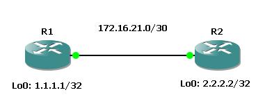
So we have quite a simple topology. Lets only use two neighboring routers because usually LDP is only used between to neighbors to exchange MPLS labels.

Here is the topology:

Challenge:
– Configure two routers to establish a LDP session between each other and use password authentication.

Well we start from theground up. So we are putting the two neihgboring interfaces online and configure an ip address.

R1(config)#int fa0/0
R1(config-if)#ip add 172.16.21.1 255.255.255.252
R1(config-if)#no shut
!
R2(config)#int fa0/0
R2(config-if)#ip add 172.16.21.2 255.255.255.252
R2(config-if)#no shut

Then for getting LDP to work we need to establish a TCP connection between those two devices on port 646. So as the two routers are neighboring and there is no device inbetween that could prevent them from doing this, we just need to activate mpls on the interfaces.

R1(config-if)#mpls label protocol ldp
R1(config-if)#mpls ip
!
R2(config-if)#mpls label prot ldp
R2(config-if)#mpls ip

Then we should see the session come up.

*Mar  1 00:24:28.567: %LDP-5-NBRCHG: LDP Neighbor 172.16.21.2:0 (1) is UP

NOTE:
When two routers are forming a LDP neighbor relationship, then you MUST BE SURE that the routers can reach each others MPLS LDP router-id. If this is not the case then the relationship will not form. Lets have a look at the current router-id.

R1#sh mpls ldp neigh
    Peer LDP Ident: 172.16.21.2:0; Local LDP Ident 172.16.21.1:0
        TCP connection: 172.16.21.2.64452 - 172.16.21.1.646
        State: Oper; Msgs sent/rcvd: 4/4; Downstream
        Up time: 00:00:29
        LDP discovery sources:
          FastEthernet0/0, Src IP addr: 172.16.21.2
        Addresses bound to peer LDP Ident:
          172.16.21.2

Here you can see the local used router-id “aka LDP ident”. Of course R1 reaches R2´s router-id-address because they are directly connected. Lets change the router-ids and create some loopback interfaces.

R1(config)#int lo0
R1(config-if)#ip address 1.1.1.1 255.255.255.255
R1(config-if)#exit
R1(config)#mpls ldp router-id lo0 force
!
R2(config)#int lo0
R2(config-if)#ip address 2.2.2.2 255.255.255.255
R2(config-if)#exit
R2(config)#mpls ldp router-id lo0 force

Lets see what happens.

*Mar  1 00:26:35.783: %LDP-5-NBRCHG: LDP Neighbor 172.16.21.1:0 (1) is DOWN (TCP connection closed by peer)

Well on both routers we get messages that the LDP relationship is down. That is because the TCP session of LDP on port 646 is sourced by the router-id-interface which is loopback0 of both routers. And as both routers dont know a way back to the opposite loopback address (we did not configure a routing protocol)…


R1#sh ip route 2.2.2.2
% Network not in table
!
R2#sh ip route 1.1.1.1
% Network not in table

…we cannot get it to work. What we need to do is to let the routers know about the other loopback address or “ldp router-id” respectively. Lets do it the quick way and enable ospf everywhere.


R1(config)#router ospf 1
R1(config-router)#network 0.0.0.0 255.255.255.255 are 0
!

R2(config)#router ospf 1
R2(config-router)#network 0.0.0.0 255.255.255.255 are 0

Lets check the routing tables.


*Mar  1 00:33:04.067: %OSPF-5-ADJCHG: Process 1, Nbr 2.2.2.2 on FastEthernet0/0 from LOADING to FULL, Loading Done
R1#sh ip route 2.2.2.2
Routing entry for 2.2.2.2/32
  Known via "ospf 1", distance 110, metric 11, type intra area
  Last update from 172.16.21.2 on FastEthernet0/0, 00:00:02 ago
  Routing Descriptor Blocks:
  * 172.16.21.2, from 2.2.2.2, 00:00:02 ago, via FastEthernet0/0
      Route metric is 11, traffic share count is 1
!
R2#sh ip route 1.1.1.1
Routing entry for 1.1.1.1/32
  Known via "ospf 1", distance 110, metric 11, type intra area
  Last update from 172.16.21.1 on FastEthernet0/0, 00:00:36 ago
  Routing Descriptor Blocks:
  * 172.16.21.1, from 1.1.1.1, 00:00:36 ago, via FastEthernet0/0
      Route metric is 11, traffic share count is 1

And almost directly after OSPF has converged we get our message that LDP has succeeded.


R1#
*Mar  1 00:33:09.599: %LDP-5-NBRCHG: LDP Neighbor 2.2.2.2:0 (1) is UP
!
R2#
*Mar  1 00:33:00.739: %LDP-5-NBRCHG: LDP Neighbor 1.1.1.1:0 (1) is UP

Ok so far so good. Then lets do some authentication here. We will use the password “cisco” to authenticate both machines to each other.

NOTE:
When configuring the neighbor authentication with LDP you need to specify the neighboring router-id address, not the interface address you are neighboring to!
AND as soon as you configure a password the session will be cleared, so pay attention when you are in a production network and take a maintenance outage window.


R1(config)#mpls ldp neighbor 2.2.2.2 password CISCO123
R1(config)#
*Mar  1 00:36:36.887: %LDP-5-NBRCHG: LDP Neighbor 2.2.2.2:0 (1) is DOWN (Session's MD5 password changed)
!
R2(config)#mpls ldp neighbor 1.1.1.1 password CISCO123
R2(config)#
*Mar  1 00:37:30.939: %LDP-5-NBRCHG: LDP Neighbor 1.1.1.1:0 (1) is UP

As soon as both machines are properly configured, the LDP session is back again!

I hope you enjoyed it.
Check out part 2, where I will show you some debugs and some troubleshooting action with LDP in combination with passwords.

Feel free to comment!
Regards!
Markus
Posted in MPLS | Tagged , , , , , , , , , , , , , , , | 4 Comments

misc: optimzation in the layout of the blog labs

Hi everybody!

I recognized that my scenarios with the cisco specific outputs the output mostly looked like crap.

This way:

Router#sh ip route
Codes: C - connected, S - static, R - RIP, M - mobile, B - BGP
D - EIGRP, EX - EIGRP external, O - OSPF, IA - OSPF inter area
N1 - OSPF NSSA external type 1, N2 - OSPF NSSA external type 2
E1 - OSPF external type 1, E2 - OSPF external type 2
i - IS-IS, su - IS-IS summary, L1 - IS-IS level-1, L2 - IS-IS level-2
ia - IS-IS inter area, * - candidate default, U - per-user static route
o - ODR, P - periodic downloaded static route


Gateway of last resort is not set

1.0.0.0/32 is subnetted, 1 subnets
C 1.1.1.1 is directly connected, Loopback0
Router#

This was due to the fact that I did not use the right operator in the text mode of wordpress. I used the “code” value and not “code” in combination with “pre”. With that combination it looks better now!


Router#sh ip route
Codes: C - connected, S - static, R - RIP, M - mobile, B - BGP
       D - EIGRP, EX - EIGRP external, O - OSPF, IA - OSPF inter area
       N1 - OSPF NSSA external type 1, N2 - OSPF NSSA external type 2
       E1 - OSPF external type 1, E2 - OSPF external type 2
       i - IS-IS, su - IS-IS summary, L1 - IS-IS level-1, L2 - IS-IS level-2
       ia - IS-IS inter area, * - candidate default, U - per-user static route
       o - ODR, P - periodic downloaded static route

Gateway of last resort is not set     1.0.0.0/32 is subnetted, 1 subnets
C       1.1.1.1 is directly connected, Loopback0
Router#

So in the future posts there will be more comfort for you!

Regards!
Markus

Posted in Misc, Uncategorized | Tagged , , , , , , , , , , , , , | 1 Comment

mpls: pseudowire emulation / any tansport over mpls – interconnecting sites via layer 2 – (part 2)

Hi again!
Now its time for part 2 of the MPLS Layer 2 interconection between two sites.

Challenge:
– interconnect two sites via PEM but without an MPLS enabled service provider network

Preconfigured & given:
– topology of Part 1
– CORE routers dont run MPLS on their backbone interfaces

So here we go. First we deconfigure MPLS from the core routers and check if everything is the way we want it to.

CORE1(config)#int fa0/0
CORE1(config-if)#no mpls ip
!
CORE2(config)#int fa0/0
CORE2(config-if)#no mpls ip
CORE2(config)#int fa0/1
CORE2(config-if)#no mpls ip
!
CORE3(config)#int fa0/0
CORE3(config-if)#no mpls ip

CORE2#sh mpls int
Interface IP Tunnel Operational

No output for the MPLS switching! Perfect! So now we are sure that CORE2 will definitely dont do any MPLS forwarding.
Now we want to use ATOM/PEM, but the problem is that this technology relies on MPLS. Hm…so what are we going to do now. Well…lets use a GRE tunnel to do that. The tunnel is built between the loopbacks of CORE1 and CORE3.

CORE1(config)#int tun 0
CORE1(config-if)#tunnel mode gre ip
CORE1(config-if)#tunnel source lo0
CORE1(config-if)#tunnel destination 3.3.3.3
CORE1(config-if)#ip address 13.13.13.1 255.255.255.252
!
CORE3(config)#int tun0
CORE3(config-if)#tunnel mode gre ip
CORE3(config-if)#tunnel source lo0
CORE3(config-if)#tunnel destination 1.1.1.1
CORE3(config-if)#ip address 13.13.13.2 255.255.255.252

Check if the tunnels are working!

CORE3#ping 13.13.13.1 so tun0

Type escape sequence to abort.
Sending 5, 100-byte ICMP Echos to 13.13.13.1, timeout is 2 seconds:
Packet sent with a source address of 13.13.13.2
!!!!!
Success rate is 100 percent (5/5), round-trip min/avg/max = 108/136/156 ms
CORE3#

Fine! So as any traffic going through the tunnel interfaces is encapsulated in GRE, well LDP should be as well. We now activate LDP on those two interfaces

CORE1(config)#int tun0
CORE1(config-if)#mpls ip
!
CORE3(config)#int tun0
CORE3(config-if)#mpls ip

So far so good lets check the neighbors and the interfaces.

CORE3#sh mpls ldp neigh
Peer LDP Ident: 1.1.1.1:0; Local LDP Ident 3.3.3.3:0
TCP connection: 1.1.1.1.646 - 3.3.3.3.17830
State: Oper; Msgs sent/rcvd: 11/11; Downstream
Up time: 00:00:21
LDP discovery sources:
Tunnel0, Src IP addr: 13.13.13.1
Addresses bound to peer LDP Ident:
172.16.21.1 1.1.1.1 13.13.13.1
CORE3#sh mpls int
Interface IP Tunnel Operational
Tunnel0 Yes (ldp) No Yes

Ok looking good. So now we will try to do “xconnect” the two tunnel inteface addresses.

CORE1(config)#int fa0/1
CORE1(config-if)#xconnect 13.13.13.2 12 pw-class PWC-SITE-1-2
!
CORE3(config)#int fa0/1
CORE3(config-if)#xconnect 13.13.13.1 12 pw-class PWC-SITE-1-2

As we configure it we get an error message that says:

*Mar 1 03:02:07.303: %ATOM_TRANS-4-CONFIG: 13.13.13.1 mismatches the peer router id 1.1.1.1

Well the Problem is that in general the highest loopback is chosen as LDP router-id. ATOM needs to connect to the router-id ip address (at least thats my point of knowledge). And the tunnel ip address is not equal to the router-id. Well you could change that with the “mpls ldp router-id tunnel0 force” command but the problem is that when you use that in production network you can get into trouble. Here you should create a new loopback address, lets say Lo1 and then for all PEM/ATOM connections use that IP address with static routing over the tunnels. Well lets just do this.

CORE1(config)#int lo1
CORE1(config-if)#ip address 11.11.11.11 255.255.255.255
CORE1(config-if)#mpls ldp router-id lo1 force
!
CORE3(config)#int lo1
CORE3(config-if)#ip address 33.33.33.33 255.255.255.255
CORE3(config-if)#mpls ldp router-id lo1 force

NOTE: When changing the router-id, all LDP neighbor relationships will go down! Keep that in mind when you are going to do this in a production network.

Goal of this step was to create loopback addresses that can be used for creating xconnect peerings AND that traffic should go through the tunnel interface. so lets create static routes here.

CORE1(config)#ip route 33.33.33.33 255.255.255.255 tun0
!
CORE3(config)#ip route 11.11.11.11 255.255.255.255 tun0

Reachability check!

CORE3#ping 11.11.11.11 so lo1

Type escape sequence to abort.
Sending 5, 100-byte ICMP Echos to 11.11.11.11, timeout is 2 seconds:
Packet sent with a source address of 33.33.33.33
!!!!!
Success rate is 100 percent (5/5), round-trip min/avg/max = 64/129/236 ms

Looking good. So next step is to reconfigure the xconnect statements.

CORE1(config)#int fa0/1
CORE1(config-if)#no xconnect 13.13.13.2 12
CORE1(config-if)#xconnect 33.33.33.33 12 pw-class PWC-SITE-1-2
!
CORE3(config)#int fa0/1
CORE3(config-if)#no xconnect 13.13.13.1 12
CORE3(config-if)#xconnect 11.11.11.11 12 pw-class PWC-SITE-1-2

Give it some time to converge and then check the VC details.

CORE1#sh mpls l2transport vc

Local intf Local circuit Dest address VC ID Status
------------- -------------------------- --------------- ---------- ----------
Fa0/1 Ethernet 33.33.33.33 12 UP

Looks good! Lets do a basic ICMP test with standard size and then lets have a look at the additional headers we created.

SITE1#ping 10.10.10.2 rep 10

Type escape sequence to abort.
Sending 10, 100-byte ICMP Echos to 10.10.10.2, timeout is 2 seconds:
!!!!!!!!!!
Success rate is 100 percent (10/10), round-trip min/avg/max = 52/135/236 ms

Cool it works. When we capture the traffic between CORE1 and CORE2 we should see GRE encapsulated traffic as MPLS is disabled on CORE2.

As we can see there is an additional GRE header which also takes space (4 Byte) and as GRE is an IP encapsulation technology, the frames dont get encapsulated directly into MPLS. Everything that goes through the tunnel is encapsulated into an IP packet so here we get another 20Bytes.

Well as you can see there is only one MPLS header! Guess why! Penultimate Hop Popping (PHP) is in use per default. And as we only have one hop here (between the tunnel endpoints) there is no need for a outer transport label! So you can only see the VC label.

Lets count everything together to calculate the required MTU size of the backbone interfac
es.

The new L2 payload size (MTU) for our backbone interfaces is therefore 20 + 4 + 4 + 14 + 1500 + 4 = 1546 Bytes. Lets try this now.

CORE1(config)#int fa0/0
CORE1(config-if)#mtu 1546
!
CORE2(config)#int fa0/0
CORE2(config-if)#mtu 1546
CORE2(config-if)#int fa0/1
CORE2(config-if)#mtu 1546
!
CORE3(config)#int fa0/0
CORE3(config-if)#mtu 1546

Take some time to let ISIS reconverge.

SITE1#ping 10.10.10.2 rep 10 size 1500 df

Type escape sequence to abort.
Sending 10, 1500-byte ICMP Echos to 10.10.10.2, timeout is 2 seconds:
Packet sent with the DF bit set
!!!!!!!!!!
Success rate is 100 percent (10/10), round-trip min/avg/max = 100/165/208 ms

Works!
So have fun with that scenario and feel free to comment!

Regards!
Markus
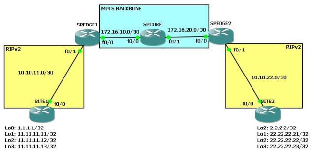
Posted in MPLS | Tagged , , , , , , , , , , , , , | Leave a comment

mpls: pseudowire emulation / any tansport over mpls – interconnecting sites via layer 2 – (part 1)

Hi everybody!
Today I am going to introduce a new challenge that takes care of MPLS and pseudowire emulation.

Challenge:
– connect two sites via a MPLS VPN Backbone at layer 2

Given:
– a “SP” network without MPLS capabilities (yet), only layer 3 routing

Preconfigured:
– ip addresses of the core routers
– ISIS as routing protocol for routing the 172.16.x.x networks and the loopback interfaces

So lets start:
First of all we do a quick routing table lookup on the core routers to see if we have full rechability between the loopbacks of the cores.

CORE3#ping 1.1.1.1 so lo0

Type escape sequence to abort.
Sending 5, 100-byte ICMP Echos to 1.1.1.1, timeout is 2 seconds:
Packet sent with a source address of 3.3.3.3
!!!!!
Success rate is 100 percent (5/5), round-trip min/avg/max = 56/75/124 ms
CORE3#ping 2.2.2.2 so lo0

Type escape sequence to abort.
Sending 5, 100-byte ICMP Echos to 2.2.2.2, timeout is 2 seconds:
Packet sent with a source address of 3.3.3.3
!!!!!
Success rate is 100 percent (5/5), round-trip min/avg/max = 12/59/92 ms
CORE3#

CORE3#sh ip route
Codes: C - connected, S - static, R - RIP, M - mobile, B - BGP
D - EIGRP, EX - EIGRP external, O - OSPF, IA - OSPF inter area
N1 - OSPF NSSA external type 1, N2 - OSPF NSSA external type 2
E1 - OSPF external type 1, E2 - OSPF external type 2
i - IS-IS, su - IS-IS summary, L1 - IS-IS level-1, L2 - IS-IS level-2
ia - IS-IS inter area, * - candidate default, U - per-user static route
o - ODR, P - periodic downloaded static route

Gateway of last resort is not set

1.0.0.0/32 is subnetted, 1 subnets
i L1 1.1.1.1 [115/30] via 172.16.32.1, FastEthernet0/0
2.0.0.0/32 is subnetted, 1 subnets
i L1 2.2.2.2 [115/20] via 172.16.32.1, FastEthernet0/0
3.0.0.0/32 is subnetted, 1 subnets
C 3.3.3.3 is directly connected, Loopback0
172.16.0.0/30 is subnetted, 2 subnets
C 172.16.32.0 is directly connected, FastEthernet0/0
i L1 172.16.21.0 [115/20] via 172.16.32.1, FastEthernet0/0

Looks good. Next step is choosing the technology we want to use. In our case we will use “pseudowire emulation” or “any transport over mpls” or whatever it is called :).
That technology requires MPLS to be enabled within the service provider network. So we will do this.

NOTE: We dont need MP-BGP here, because PEM (pseudowire emulation) only needs traffic to be encaspulated into MPLS to be transported end to end. There is no need for exchanging VRF information over BGP extended communities.


CORE1(config-if)#mpls ip
CORE1(config-if)#
!
CORE2(config)#int fa0/0
CORE2(config-if)#mpls ip
CORE2(config-if)#int fa0/1
CORE2(config-if)#mpls ip
!
CORE3(config)#int fa0/0
CORE3(config-if)#mpls ip

On Core 2 we will do a lookup into the LDP neighbor table to see if the adjacencies have been built.

CORE2#sh mpls int
Interface IP Tunnel Operational
FastEthernet0/0 Yes (ldp) No Yes
FastEthernet0/1 Yes (ldp) No Yes
CORE2#sh mpls ldp neigh
Peer LDP Ident: 1.1.1.1:0; Local LDP Ident 2.2.2.2:0
TCP connection: 1.1.1.1.646 - 2.2.2.2.47369
State: Oper; Msgs sent/rcvd: 9/9; Downstream
Up time: 00:01:21
LDP discovery sources:
FastEthernet0/0, Src IP addr: 172.16.21.1
Addresses bound to peer LDP Ident:
172.16.21.1 1.1.1.1
Peer LDP Ident: 3.3.3.3:0; Local LDP Ident 2.2.2.2:0
TCP connection: 3.3.3.3.43937 - 2.2.2.2.646
State: Oper; Msgs sent/rcvd: 8/8; Downstream
Up time: 00:00:54
LDP discovery sources:
FastEthernet0/1, Src IP addr: 172.16.32.2
Addresses bound to peer LDP Ident:
172.16.32.2 3.3.3.3

Looks good! Messages have been exchanged between the machines.
Now we will create a “pseudowire class” to set the method (in our case MPLS) which should be used to encapsulate packets.

NOTE: we only need to perform this step on the ingress and egress routers (where the emulation takes place). All other routers only need to perform label switching.

CORE1(config)#pseudowire-class PWC-SITE-1-2
CORE1(config-pw-class)#encapsulation mpls
!
CORE3(config)#pseudowire-class PWC-SITE-1-2
CORE3(config-pw-class)#encapsulation mpls

Now we are going to use those ones with the “xconnect” command under the interfaces we want to have a Layer2 connection with each other. This will be fa0/1 of CORE1 and CORE3.
Under the interface level we also need to type in an ip address. Well kind of strange but that is atually the ip address of the peering router that has the other side of the “virtual L2 line” in his stack. What makes sense here is to enter the loopback interface of the corresponding machines.

CORE1(config-if-xconn)#int fa0/1
CORE1(config-if)#xconnect 3.3.3.3 12 pw-class PWC-SITE-1-2
!
CORE3(config-if-xconn)#int fa0/1
CORE3(config-if)#xconnect 1.1.1.1 12 pw-class PWC-SITE-1-2

What now is heading into our eyes is another LDP neighborship?!?!

*Mar 1 00:21:36.015: %LDP-5-NBRCHG: LDP Neighbor 1.1.1.1:0 (2) is UP

Well what the hell is this about? Well that is a targeted hello session that is needed to exchange pseudowire information between the two corresponding routers. Background to that matter is the following: The routers form a LDP adjacency via unicast. Reason for that is that they need to talk to each other about the MPLS header for the VC (the pseudowire virtual channel) as the packets are first sent from CORE1 to CORE3 via MPLS (the transport label) and then the transport label is stripped of. The second label then gives information about the corresponding VC.

The config is done right now! Now we gotta check if the VC (virtual channel) is up.
NOTE: Here you can also see the “MPLS VC Labels” that have been exchanged between CORE1 and CORE3. So dont wonder when you are sniffing the MPLS packets and see the labels 19 and 20 show up in your wireshark output and they dont when doing a “sh mpls ldp binding”.

CORE3#sh mpls l2transport vc det
Local interface: Fa0/1 up, line protocol up, Ethernet up
Destination address: 1.1.1.1, VC ID: 12, VC status: up
Next hop: 172.16.32.1
Output interface: Fa0/0, imposed label stack {18 19}
Create time: 00:08:01, last status change time: 00:07:59
Signaling protocol: LDP, peer 1.1.1.1:0 up
MPLS VC labels: local 20, remote 19
Group ID: local 0, remote 0
MTU: local 1500, remote 1500
Remote interface description:
Sequencing: receive disabled, send disabled
VC statistics:
packet totals: receive 57, send 57
byte totals: receive 6253, send 6253
packet drops: receive 0, seq error 0, send 0
!CORE1#sh mpls l2transport vc det
Local interface: Fa0/1 up, line protocol up, Ethernet up
Destination address: 3.3.3.3, VC ID: 12, VC status: up
Next hop: 172.16.21.2
Output interface: Fa0/0, imposed label stack {19 20}
Create time: 00:29:18, last status change time: 00:08:21
Signaling protocol: LDP, peer 3.3.3.3:0 up
MPLS VC labels: local 19, remote 20
Group ID: local 0, remote 0
MTU: local 1500, remote 1500
Remote interface description:
Sequencing: receive disabled, send disabled
VC statistics:
packet totals: receive 191, send 189
byte totals: receive 21087, send 20924
packet drops: receive 0, seq error 0, send 10

Nice! Seems to look good. We will now configure some ip addresses on the routers SITE1 and SITE2 to see if we can get an L2 adjacency.

SITE1(config)#int fa0/0
SITE1(config-if)#ip add 10.10.10.1 255.255.255.0
!
SITE2(config)#int fa0/0
SITE2(config-if)#ip add 10.10.10.2 255.255.255.0

Lets try a simple icmp.

SITE1#ping 10.10.10.2

Type escape sequence to abort.
Sending 5, 100-byte ICMP Echos to 10.10.10.2, timeout is 2 seconds:
!!!!!
Success rate is 100 percent (5/5), round-trip min/avg/max = 72/131/200 ms
SITE1#sh arp
Protocol Address Age (min) Hardware Addr Type Interface
Internet 10.10.10.1 - c20e.1164.0000 ARPA FastEthernet0/0
Internet 10.10.10.2 27 c20d.1aac.0000 ARPA FastEthernet0/0

It succeeds. Well thats good :). Lets see if we can use other layer 2 protocols.

SITE1#sh cdp neigh
Capability Codes: R - Router, T - Trans Bridge, B - Source Route Bridge
S - Switch, H - Host, I - IGMP, r - Repeater

Device ID Local Intrfce Holdtme Capability Platform Port ID
CORE1 Fas 0/0 127 R S I 3725 Fas 0/1
SITE2 Fas 0/0 142 R S I 3725 Fas 0/0

Ok thats enough for now! We can see that it works. But we will test something else now. A ping with the payload of 1500 (including ip header) between the two sites with the DF bit set.

SITE1#ping 10.10.10.2 size 1500 df

Type escape sequence to abort.
Sending 5, 1500-byte ICMP Echos to 10.10.10.2, timeout is 2 seconds:
Packet sent with the DF bit set
.....
Success rate is 0 percent (0/5)

FAIL! Thats not what we wanna see. We want to use 1500bytes of mtu but we cant. Well, the reason for that is the additional headers we have used to generate the PEM. Lets do some wireshark action here. We will sniff the icmp packets between CORE1 and CORE2 to see whats happening. First we will get some packets with the standard icmp size and not with 1500 DF.

Well there is the problem, we have a little more traffic to handle with the PEM.

1x MPLS Label for transporting the packet through the MPLS network to the PEM peer (4 Byte)
1x MPLS Label that is used at the peer for identifying the correct VC (4 Byte)
1x additional Ethernet Header. Well our source frame from SITE1 is 1518 bytes long. As the COMPLETE frame is encapsulated into two MPLS headers and we are using ethernet as transport technology here, means that there needs to be a new L2 header for transporting the frame from CORE1 to CORE2 and so on (18 Byte).

So this is the initial frame that SITE1 wants to send to SITE2 (Payload/required MTU is 1500):

And this is the packet when it was encapsulated by PEM and goes on its way into the backbone (New Payload/required MTU is now 1526 Byte):

Lets configure the new required MTU.

NOTE: When changing the MTU and within the backbone the MTU on some links is different, then you wont get an OSPF or ISIS adjacency as the MTU is part of the negotiation process for such relationships.

CORE1(config-if)#mtu 1526
CORE1(config-if)#
!
CORE2(config-if)#int fa0/0
CORE2(config-if)#mtu 1526
CORE2(config-if)#int fa0/1
CORE2(config-if)#mtu 1526
!
CORE3(config)#int fa0/0
CORE3(config-if)#mtu 1526

Give ISIS or OSPF some time to reconverge if needed and then you can head on with the ICMP testing.

SITE1#ping 10.10.10.2 rep 5 size 1500 df

Type escape sequence to abort.
Sending 5, 1500-byte ICMP Echos to 10.10.10.2, timeout is 2 seconds:
Packet sent with the DF bit set
!!!!!
Success rate is 100 percent (5/5), round-trip min/avg/max = 100/160/204 ms

It works!!!

Read the next part coming up where we will do the same with the exception that the provider network (CORE2) is not capable of MPLS :).

Have fun and feel free to comment!

Regards!
Markus

Posted in MPLS, Uncategorized | Tagged , , , , , , , , , , , , , , , , | 2 Comments